Connector terminal, connector and manufacturing method of connector

一种连接器端子、连接器的技术,应用在连接装置的零部件、连接、两部件连接装置等方向,能够解决连接器端子歪斜弯折、基座结构强度降低、连接器高不合格率等问题,达到不易歪斜、增加接触面积的效果

Inactive Publication Date: 2016-02-10
CHANT SINCERE CO LTD
View PDF4 Cites 4 Cited by
  • Summary
  • Abstract
  • Description
  • Claims
  • Application Information

AI Technical Summary

Problems solved by technology

There are holes in the base of the connector corresponding to the position of the connector terminals. If the number of connector terminals increases, it means that the structural strength of the base will be reduced
In addition, since the width of the connector terminal is reduced, the structural strength of the connector terminal itself is also weak
For this type of connector, during assembly, different operators exert different forces on the connector terminals, which may cause the connector terminals to be skewed and bent, and cannot be correctly installed on the base
Moreover, since the width of the connector terminals is too small and the number is quite large, it is also difficult for the operator to directly judge with the naked eye whether the connector terminals have been assembled correctly.
Therefore, such connectors tend to have a high defect rate

Method used


Image

  • Connector terminal, connector and manufacturing method of connector
  • Connector terminal, connector and manufacturing method of connector
  • Connector terminal, connector and manufacturing method of connector

Examples


Embodiment Construction

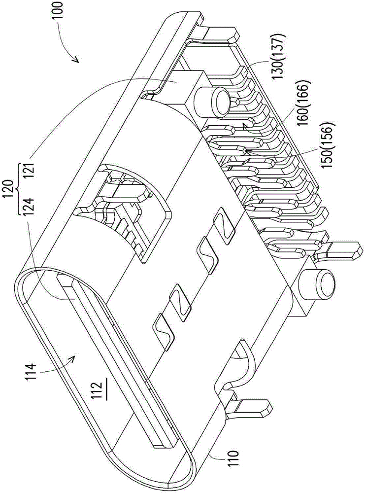
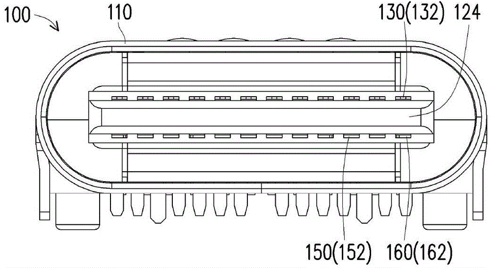
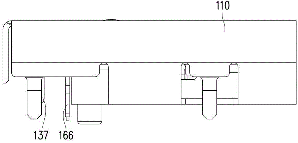
[0086] figure 1 It is a three-dimensional schematic diagram of a connector according to an embodiment of the present invention. Figure 2 to Figure 3 yes figure 1 Schematic diagrams of different viewing angles of the connector. see Figure 1 to Figure 3 , in this embodiment, the type of the connector 100 is an example of a USBC type female connector, but the type of the connector 100 is not limited thereto. The connector 100 of this embodiment includes a housing 110 , a base 120 , a plurality of first connector terminals 130 , a plurality of second connector terminals 150 and a plurality of third connector terminals 160 .

[0087] The casing 110 has an inner space 112 and an opening 114 communicating with the inner space 112 . The base 120 is disposed in the inner space 112 . In this embodiment, the material of the base 120 is an insulating material, such as a resin such as a rubber core or a polymer material, but the material of the base 120 is not limited thereto, as lo...


PUM


Abstract

The invention provides a connector terminal, comprising a body and a projection portion. The body comprises a first contact portion, a first intermediate portion, and a first connecting portion connected with each other in sequence. The first contact portion is used to contact with a pair of connector terminals. The first connecting portion is used to connect with a circuit board. The projection portion is raised on the first intermediate portion along a normal direction of a contact surface of the first contact portion. The invention also provides a connector which includes a casing, a base and the above connector terminals, and a manufacturing method of the connector. Through arranging the projection portion on the first intermediate portion of the connector terminal, an operator can push the projection portion through a jig or by hands, so as to push the first contact portion into a first groove to complete assembly. If the jig is used to push the projection portion, certain force application can be maintained, so the connector terminal does not easily incline when being installed. In manual installation, the projection portion increases contact area between an operator finger and the connector terminal, so as to improve possibility that the connector terminal is correctely installed in the base.

Description

technical field [0001] The present invention relates to a connector terminal, a connector and a method for manufacturing the connector, and in particular relates to a connector terminal, a connector and a method for manufacturing the connector with high assembly yield. Background technique [0002] At present, the common USB2.0 connectors on the market have four connector terminals arranged in a row, because the width of the USB2.0 connector is about the width of a finger, and each connector terminal also has a certain width and structural strength. When assembling, the operator can easily push the connector terminals into the base to complete the assembly, and after the assembly is completed, the operator can directly judge with the naked eye whether the connector terminals are correctly assembled. [0003] With the advancement of technology, the size of connectors is getting smaller and smaller, and the number of connector terminals is also increasing with the improvement ...

Claims


Application Information

Patent Timeline
Patent Type & Authority Applications(China)
IPC IPC(8): H01R13/02H01R43/20H01R12/71
CPCH01R12/724H01R13/405H01R24/60H01R43/205H01R2107/00
Inventor 颜铭辉许钧翔
Owner CHANT SINCERE CO LTD
Why Eureka
Try Eureka