
Positioning mechanism and laminating equipment using same

A technology of positioning mechanism and lamination equipment, applied in metal processing equipment, large fixed members, metal processing machinery parts, etc., can solve the problems of inconsistent height, skew of the second workpiece, affecting the lamination yield and so on

Inactive Publication Date: 2014-03-12
HONG FU JIN PRECISION IND (SHENZHEN) CO LTD +1
View PDF2 Cites 2 Cited by
  • Summary
  • Abstract
  • Description
  • Claims
  • Application Information

AI Technical Summary

Problems solved by technology

However, since the bottom surface of the positioning member is pressed against the periphery of the second workpiece at the same time, when the heights of the two sides of the second workpiece are inconsistent due to dimensional tolerances, it is easy to make the second workpiece skew and affect the bonding yield

Method used


Image

  • Positioning mechanism and laminating equipment using same
  • Positioning mechanism and laminating equipment using same
  • Positioning mechanism and laminating equipment using same

Examples


Embodiment Construction

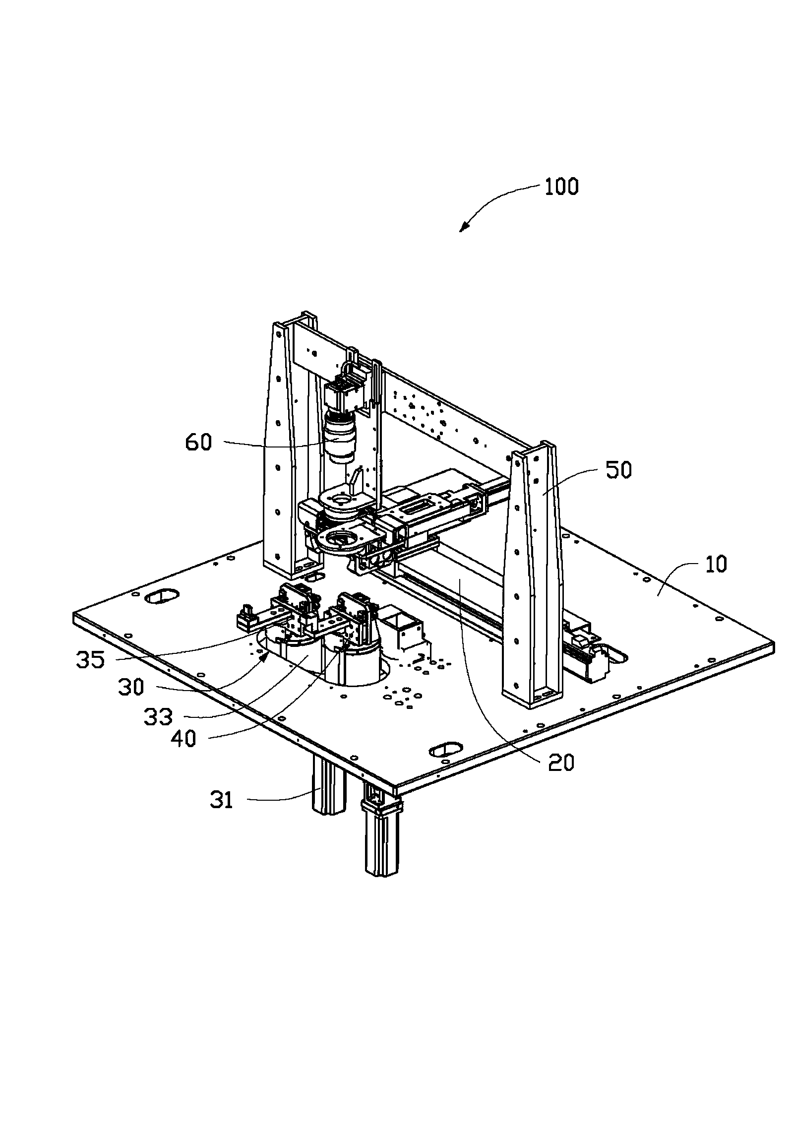
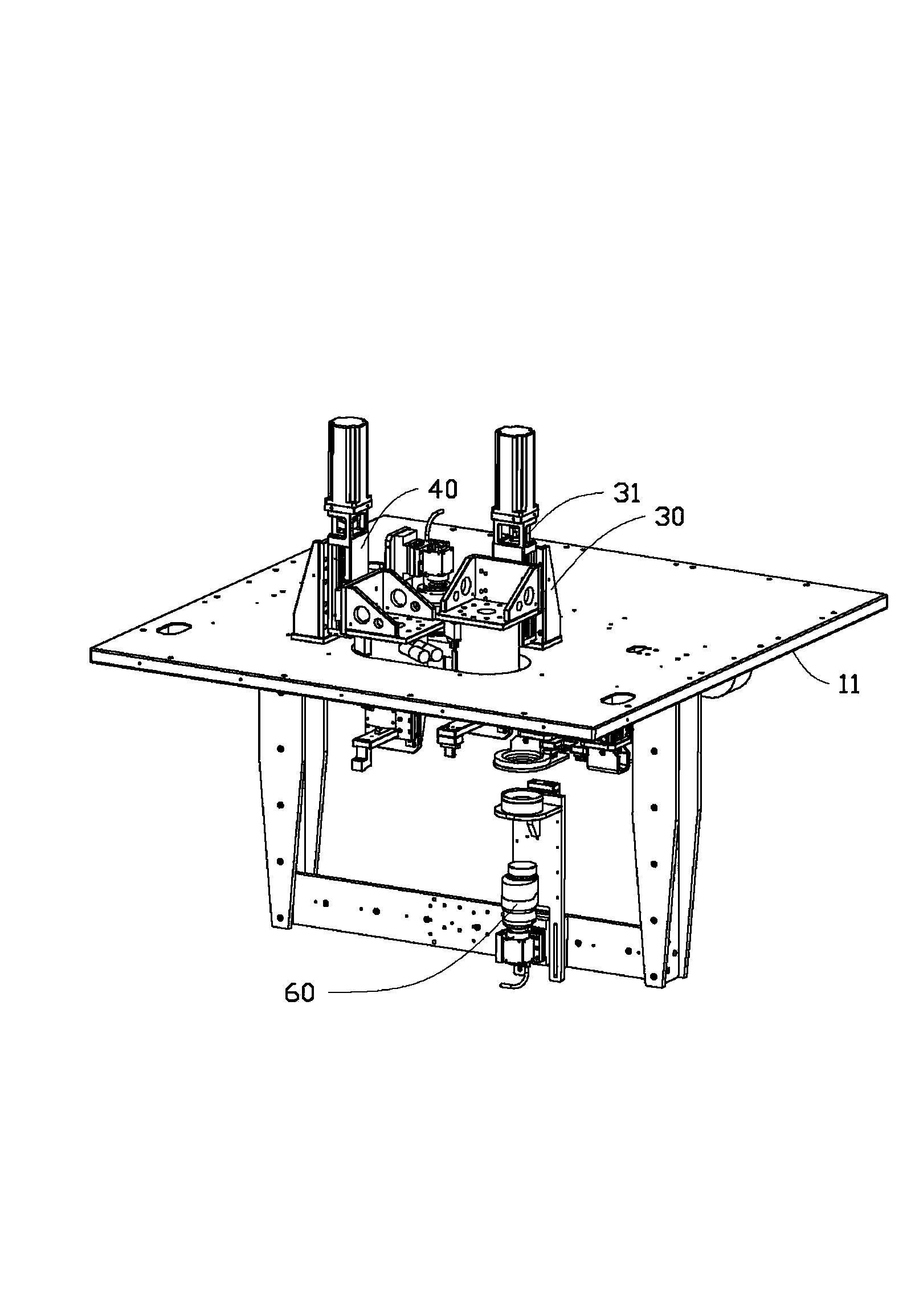
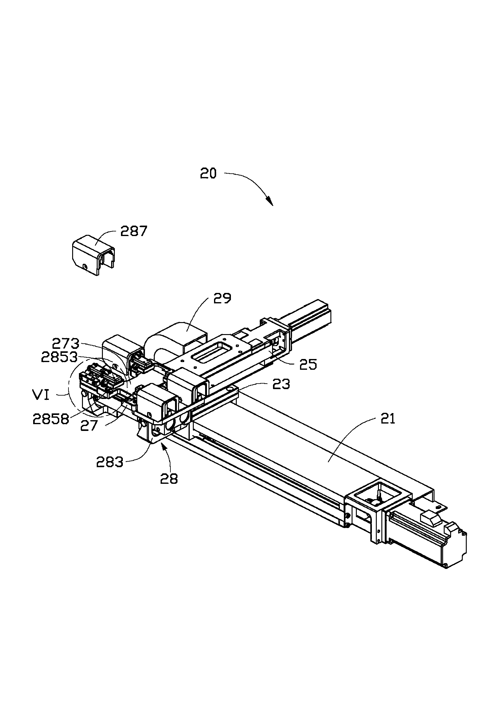
[0017] see figure 1 and figure 2 , the laminating equipment 100 of this embodiment includes a machine platform 10, a positioning mechanism 20 installed on the machine platform 10, a first laminating mechanism 30, a second laminating mechanism 40, a bracket 50, and a positioning mechanism installed on the bracket 50. The first detection module 60 and the second detection module (not shown) installed on the machine 10 . The positioning mechanism 20 is used to move and position the first workpiece (not shown). The first attaching mechanism 30 is used to attach the second workpiece (not shown) to the first workpiece, and the first detection module 60 is used to detect the positioning deviation of the second workpiece relative to the first workpiece. The second attaching mechanism 40 is used for attaching the third workpiece (not shown) to the second workpiece. The second detection module is used to detect the positioning deviation of the third workpiece relative to the first w...


PUM


Abstract

A positioning mechanism comprises a loading component and a clamping component, the clamping component comprises a driving unit, at least two positioning clamps and at least two slide units; the driving unit is arranged on one side of the loading component, the at least two positioning clamps are arranged on the opposite side of the loading component, the at least two positioning clamps are divided into two groups and arranged on two ends which are close to the loading component, the at least two slide units are slidingly arranged on the driving unit and moveably connected to the corresponding positioning clamps, when each slide unit slides, the sliding unit can drive the corresponding positioning clamp to move in the reverse direction of the sliding direction of the slide unit, the driving unit drives the at least two slide units to move in opposite directions so as to drive the two groups of positioning clamps, then the two groups of positioning clamps clamp a work tool from two sides of the work tool and position the work tool on the loading component. The invention also provides laminating equipment using the positioning mechanism. When the positioning mechanism is used to position a work tool, the work tool is not easy to incline and the qualified lamination rate is high.

Description

technical field [0001] The invention relates to a positioning mechanism, in particular to a positioning mechanism with two sets of positioning clips and a fitting device using the positioning mechanism. Background technique [0002] In industry, bonding equipment is often used to bond the first workpiece to the second workpiece. Before bonding, the positioning mechanism of the bonding equipment is used to position the second workpiece. The positioning mechanism includes a positioning piece and a positioning plate that cooperate with each other. A positioning cavity for accommodating the second workpiece is opened on the positioning plate, and an avoidance space communicated with the positioning cavity is formed for the first workpiece to be pressed from the avoidance space. Insert and attach to the second workpiece. When laminating, first place the second workpiece in the positioning cavity of the positioning plate, then press the positioning member against the periphery o...

Claims


Application Information

Patent Timeline
Patent Type & Authority Applications(China)
IPC IPC(8): B32B38/18
CPCB32B38/1833B32B38/18B23Q1/64B32B2315/08Y10T156/17
Inventor 张朝乾周文才雷学华陈鹏辉彭应军郎文杰
Owner HONG FU JIN PRECISION IND (SHENZHEN) CO LTD
Learn More