Robot harmonic reducer device

A harmonic reducer and robot technology, applied in the direction of transmission devices, friction transmission devices, mechanical equipment, etc., can solve the problems of large assembly errors, reduced assembly accuracy, and low power output accuracy, and achieve the goal of saving raw materials and improving assembly accuracy Effect

Inactive Publication Date: 2016-03-09
SHANDONG SHKE MACHINERY MFG
View PDF7 Cites 6 Cited by
  • Summary
  • Abstract
  • Description
  • Claims
  • Application Information

AI Technical Summary

Problems solved by technology

[0007] One is that the outer circumference of the wave generator 2 is rotationally connected to the rigid wheel 1 through the bearing support 3 and the flexible bearing 4, and the multiple components need to be processed separately and then assembled multiple times, and the assembly error is relatively large;
[0008] The second is that the outer circumference of the flexible wheel 5 is also rotationally connected with the rigid wheel 1 through the roller bearing mounting seat 6 and the cross roller bearing 7. There are also multiple parts that need to be processed separately, and then assembled multiple times, resulting in assembly errors. major defects;
[0009] The third is that the installation hole of the central axis of the flexspline 5 and the installation hole of the central axis of the wave generator 2 are required to be coaxial. In the actual assembly process, since there is no direct positioning device between the flexspline 5 and the wave generator 2, it depends entirely on The assembly accuracy of the transmission shaft determines the coaxiality between the central shaft installation hole of the flex spline 5 and the central shaft installation hole of the wave generator 2, which will lead to large errors and greatly reduce the assembly accuracy
Resulting in lower overall power output accuracy

Method used


Image

  • Robot harmonic reducer device
  • Robot harmonic reducer device
  • Robot harmonic reducer device

Examples


Embodiment Construction

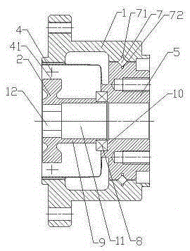
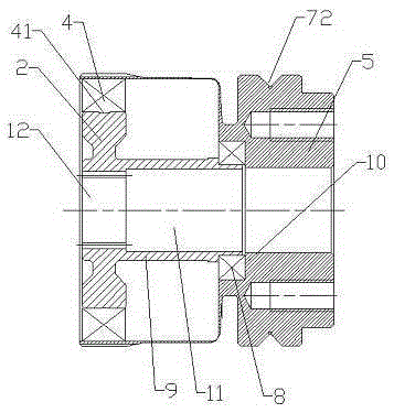
[0030] Examples such as Figure 2-4 As shown, a robot harmonic reducer device includes a rigid spline 1, a flexible spline 5 and a wave generator 2 assembled together; a coaxial positioning device is arranged between the flexible spline 5 and the wave generator 2.

[0031] The coaxial positioning device includes a positioning shaft 9 extending toward the flexspline 5 along the central axis of the wave generator 2 , and the rear end of the positioning shaft 9 is connected to the flexspline 5 through a deep groove ball bearing 8 rotatably supported.

[0032] The rear end of the positioning shaft 9 is integrally processed with a bearing mounting table 13, the deep groove ball bearing 8 is installed on the bearing mounting table 13, and the position corresponding to the rear end of the positioning shaft 9 on the flexible spline 5 is integrally processed There is a sinker 10 , and the outer end of the deep groove ball bearing 8 is located in the sinker 10 and tightly connected with...


PUM


Abstract

The invention discloses a robot harmonic reducer device. The robot harmonic reducer device comprises a rigid gear, a flexible gear and a wave generator which are assembled together. A coaxial positioning device is arranged between the flexible gear and the wave generator. The assembly accuracy between the wave generator and the flexible gear is reduced to be less than 2 microns through the coaxial positioning device, and the radial run-out error between the wave generator and the flexible gear is reduced to be less than 5 microns. According to the robot harmonic reducer device, an inner ring and an outer ring of a cross roller bearing are integrally machined on the rigid gear and the flexible gear respectively, roller pins are directly assembled, the inner ring and the outer ring are omitted, and raw materials are saved; moreover, the situation that multiple assembly errors are generated due to the fact that an inner ring, an outer ring and roller pins of a cross roller bearing are machined respectively and then assembled and finally are assembled between a rigid gear and a flexible gear is avoided. The overall assembly error is reduced to be less than 2 microns.

Description

technical field [0001] The invention relates to a harmonic reducer, in particular to a robot harmonic reducer device which increases positioning accuracy and reduces transmission errors, and belongs to the technical field of reducers. Background technique [0002] Harmonic gear reducer is a new type of reducer developed by using the principle of planetary gear transmission. Harmonic gear transmission (referred to as harmonic transmission), it is a planetary gear transmission that relies on flexible parts to generate elastic mechanical waves to transmit power and motion. [0003] Such as figure 1 As shown, the most commonly used harmonic gear reducer on the market is mainly composed of three basic components: A. Rigid gear with an inner ring gear, referred to as rigid gear 1, which is equivalent to the center gear in the planetary system; [0004] B. A flexible gear with an external ring gear, referred to as a flexible gear 5, which is equivalent to a planetary gear; [00...

Claims


Application Information

Patent Timeline
Patent Type & Authority Applications(China)
IPC IPC(8): F16H13/04
CPCF16H13/04
Inventor 汤承龙
Owner SHANDONG SHKE MACHINERY MFG
Why Eureka
Try Eureka