Method for manufacturing air compressor moving plate

A technology of air compressor and production method, which is applied in the direction of machine/engine, rotary piston type/swing piston type pump parts, mechanical equipment, etc. Uniformity, easy breakage and other problems, to achieve the effect of reducing production costs

Inactive Publication Date: 2011-10-05
NINGBO QUNXING POWDER METALLURGY
View PDF0 Cites 0 Cited by
  • Summary
  • Abstract
  • Description
  • Claims
  • Application Information

AI Technical Summary

Problems solved by technology

The cost of the moving plate processed by this molding method is relatively high, and the welding part is easy to break during use, and because the three parts are cast separately, it is difficult to ensure the consistency of hardness and uniform texture of the three parts sex

Method used


Image

  • Method for manufacturing air compressor moving plate
  • Method for manufacturing air compressor moving plate
  • Method for manufacturing air compressor moving plate

Examples


Embodiment 1

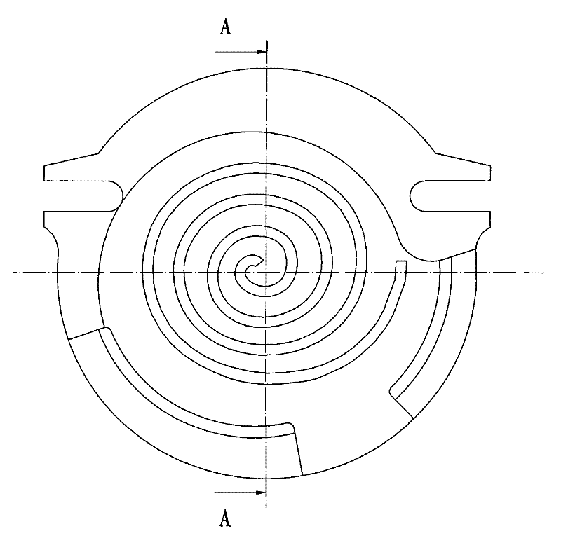
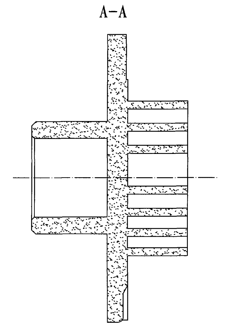
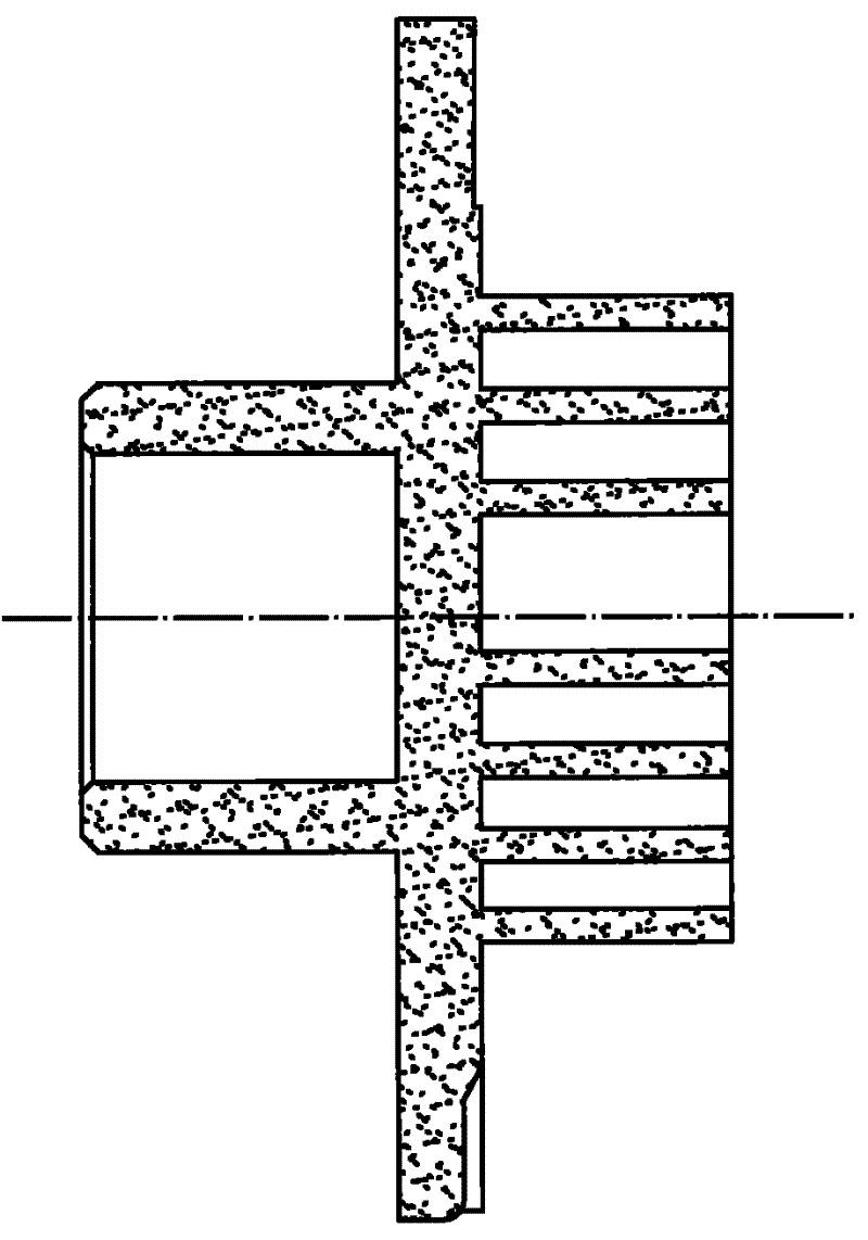
[0027] ①Mold making: Use a lathe to process the mold of the pipe body 3, use a wire cutting machine to process the mold of the spiral groove 1, and use a CNC forming machine to process the mold except the spiral groove and the remaining part of the pipe body;

[0028] ②Mixed powder: Use a mixing cylinder to mix the atomized powder and alloy powder according to the mass fraction of: 70% of atomized powder and 30% of alloy powder;

[0029] ③Pressing: Use a dry powder forming hydraulic press to press the powder mixed in step ② according to the mold prepared in step ①, and the pressure value is 1000N;

[0030] ④Sintering: Press the molded workpiece in step ③ in a sintering furnace, the sintering temperature is 1100°C, and the firing temperature is 40°C;

[0031] ⑤ Finishing: The workpiece after sintering in step ④ is ground and polished to form a finished product.

[0032] The mass fraction of the alloy powder containing iron is 90%, and the mass fraction of the alloy powder cont...

Embodiment 2

[0038] ①Mold making: Use a lathe to process the mold of the pipe body 3, use a wire cutting machine to process the mold of the spiral groove 1, and use a CNC forming machine to process the mold except the spiral groove and the remaining part of the pipe body;

[0039] ②Mixed powder: Use a mixing cylinder to mix the atomized powder and alloy powder according to the mass fraction of: 65% of atomized powder and 35% of alloy powder;

[0040] ③Pressing: Use a dry powder forming hydraulic press to press the powder mixed in step ② according to the mold prepared in step ①, and the pressure value is 800N;

[0041] ④Sintering: Press the formed workpiece in the sintering furnace sintering step ③, the sintering temperature is 1000°C, and the firing temperature is 45°C;

[0042] ⑤ Finishing: The workpiece after sintering in step ④ is ground and polished to form a finished product.

[0043] The mass fraction of the alloy powder containing iron is 92%, and the mass fraction of the alloy pow...


PUM


Abstract

The invention provides a method for manufacturing air compressor moving plate, comprising: a mould of a pipe body is processed by a lathe; a mould of a spiral groove is processed by a linear cutting machine, and moulds of the rest parts except the spiral groove and the pipe body by a numerical control forming machine tool; atomized powder and reduced iron powder are mixed together and processed by a mixing cylinder according to the mass percent: 65-70% of atomized powder and 30-35% of alloy powder; the mixed powder is pressed and shaped inside the prepared moulds by a dry powder shaping hydraulic machine, and the pressure value is 800-1000N; molded workpieces are manufactured by being sintered and pressed in a sintering furnace, the sintering temperature is 1000-1100 DEG C, and the tapping temperature does not excess 45 DEG C; the sintered workpieces are ground, polished and the like, and the finished products can be formed. The method has the advantages that by adopting one-step molding technique, a plurality of parts are avoided being respectively processed, and the production cost can be reduced; after being extruded and sintered by the powder shaping machine, the finished product has uniform hardness, so as not to be easy to break.

Description

technical field [0001] The invention relates to a manufacturing method of metal parts, in particular to a manufacturing method of an air compressor moving plate. Background technique [0002] A moving plate is a component used in air compressors such as figure 1 and figure 2 As shown, it includes a spiral groove, a disc and a tube body, and the spiral groove is connected with the tube body through the disc. In the prior art, the casting method is used to process the moving plate, and the three parts are cast separately, then welded, and finally finished by grinding and polishing. The moving plate processed by this molding method has a high cost, and the welded part is easy to break during use. Moreover, because the three parts are cast separately, it is difficult to ensure the consistency of hardness and uniformity of the texture of the three parts. sex. SUMMARY OF THE INVENTION [0003] The purpose of the present invention is to overcome the deficiencies of the prior...

Claims


Application Information

Patent Timeline
Patent Type & Authority Patents(China)
IPC IPC(8): F04C29/00B22F3/16
Inventor 潘成群
Owner NINGBO QUNXING POWDER METALLURGY
Why Eureka
Try Eureka