

Novel stand column type cantilever crane
A column-type and crane technology, which is applied to cranes and other directions, can solve the problems that the position of the column-type cantilever crane cannot be moved, the cantilever and column are not easy to disassemble, and the scope of use is limited. material effect
- Summary
- Abstract
- Description
- Claims
- Application Information
AI Technical Summary
Problems solved by technology
Method used
Image

Examples
Embodiment 1
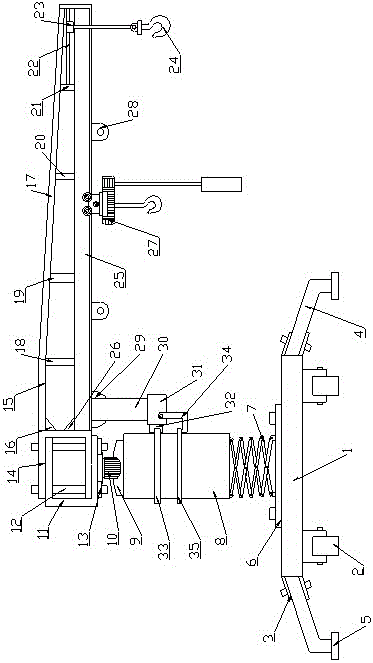
[0016] Such as figure 1 As shown, a novel column type cantilever crane includes a base 1, the lower side of the base 1 is provided with a universal sliding wheel 2, the four corners of the base 1 are provided with connecting plates 3, and the connecting plates 3 The legs 4 are connected by bolts, the bottom of the legs 4 is provided with a non-slip base 5, and the upper side of the base 1 is connected with a lifting platform 6 and a lifting device 7 matched with the lifting platform 6 through bolts. The upper end of the lifting device 7 is connected with a column 8, and the upper end of the column 8 is provided with a motor fixing seat 9 and a driving motor 10 matched with the motor fixing seat 9. The driving motor 10 is connected with a fixing buckle A11, and the fixing The buckle A11 is provided with a through hole matched with the output shaft of the drive motor 10, and the upper and lower parts of the fixed buckle A11 are provided with threaded holes, and the fixed buckle ...
Embodiment 2
[0019] Such as figure 1As shown, a novel column type cantilever crane includes a base 1, the lower side of the base 1 is provided with a universal sliding wheel 2, the four corners of the base 1 are provided with connecting plates 3, and the connecting plates 3 The legs 4 are connected by bolts, the bottom of the legs 4 is provided with a non-slip base 5, and the upper side of the base 1 is connected with a lifting platform 6 and a lifting device 7 matched with the lifting platform 6 through bolts. The upper end of the lifting device 7 is connected with a column 8, and the upper end of the column 8 is provided with a motor fixing seat 9 and a driving motor 10 matched with the motor fixing seat 9. The driving motor 10 is connected with a fixing buckle A11, and the fixing The buckle A11 is provided with a through hole matched with the output shaft of the drive motor 10, and the upper and lower parts of the fixed buckle A11 are provided with threaded holes, and the fixed buckle A...
PUM
 Abstract
Description
Claims
Application Information