
A driving device for an ultrasonic flaw detector

A driving device and flaw detector technology, which is used in measuring devices, material analysis using sonic/ultrasonic/infrasonic waves, instruments, etc. The effect of improved speed change and accurate flaw detection

Active Publication Date: 2019-03-26
常州常瑞轨道交通科技有限公司
View PDF6 Cites 0 Cited by
  • Summary
  • Abstract
  • Description
  • Claims
  • Application Information

AI Technical Summary

Problems solved by technology

[0003] However, there are still some technical problems in the above-mentioned technical solution: 1. When using the rotating drum to drive the chain forward, the number of turns of the cable drag chain on the rotating drum will gradually decrease, and the forward speed of the chain will slow down, so the speed of the probe will become smaller. Slow, the probe's walking speed is unstable, which affects the accuracy of flaw detection; 2. The number of coils of the cable drag chain on the rotating drum will gradually increase when retreating, and the retreat speed will become faster, and the probe rod will retreat too fast, which will affect the probe. Flaw detection accuracy; 3. It cannot be driven by a high-power motor, because the chain on the rotating drum will bend abnormally if the forward speed is too fast. However, it is very important to shorten the inspection time for the hollow axle shaft about 2000mm during flaw detection.

Method used


Image

  • A driving device for an ultrasonic flaw detector
  • A driving device for an ultrasonic flaw detector
  • A driving device for an ultrasonic flaw detector

Examples


Embodiment 1

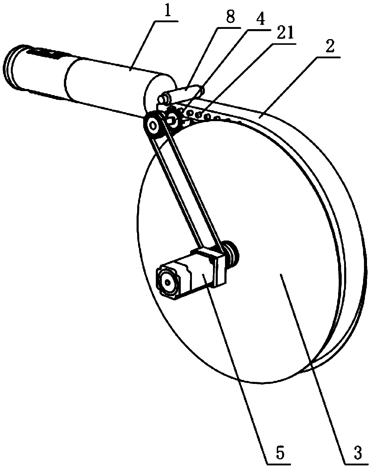
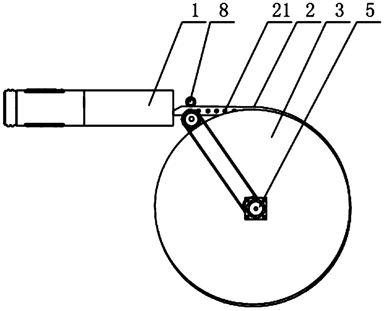
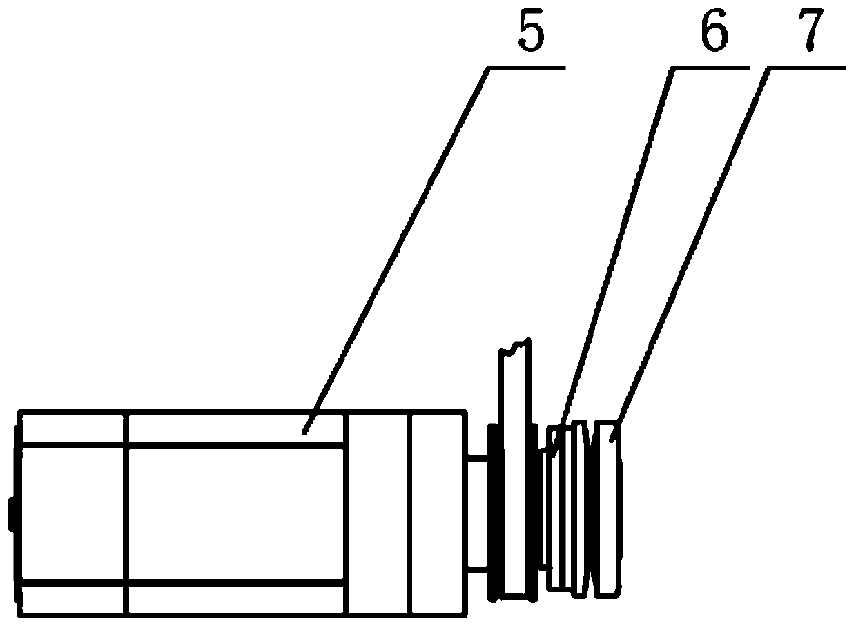
[0023] Such as Figure 1-3 As shown, the driving device of the ultrasonic flaw detector in this embodiment includes a probe rod 1 and a cable drag chain 2 rigidly connected with the probe rod 1. A flaw detection head is installed on the outer peripheral surface of one end of the probe rod 1. The flaw detection head on the probe rod 1 Enter the hollow axle for flaw detection, and the signal cable pulled out by the flaw detection head is stored and fixed in the cable drag chain 2, and the cable drag chain 2 is coiled on the outer peripheral surface of the rotating drum 3, specifically, the outer peripheral surface of the rotating drum 3 An annular groove is provided, and the cable drag chain 2 is coiled in the annular groove. The sprockets matched with the cable drag chain 2 are arranged in the annular groove, and the rotating drum 3 drives the cable drag chain 2 through the sprockets.

[0024] In order to improve the walking speed and flaw detection accuracy of the probe rod 1,...


PUM


Abstract

The invention relates to the technical field of ultrasonic flaw detection, in particular to a driving device of an ultrasonic flaw-detecting machine. The driving device comprises a detecting rod and a cable drag chain rigidly connected with the detecting rod, wherein the cable drag chain winds around the external circumference of a rotary drum driven by a motor; the motor drives the cable drag chain to advance through a chain wheel clutch and drives the cable drag chain to retreat through the rotary drum; when the motor drives the cable drag chain to advance through the chain wheel clutch, the highest speed can reach 100 mm / s, and the problem of inaccurate flaw detection caused by unstable speed of the cable drag chain when directly driven by the rotary drum is solved; during extraction, the detecting rod is driven by the rotary drum to retreat through the cable drag chain, the lowest retreating speed is 2 mm / s, with adoption of the driving mode, the flow detecting speed changes from 2 mm / s to 100 mm / s, wide-range speed change is realized, and the flaw detecting precision is improved; meanwhile, the retreating speed is limited by a torque limiter, so that the retreating speed of the detecting rod is stable, and flaw detection is more accurate.

Description

technical field [0001] The invention relates to the technical field of ultrasonic flaw detection, in particular to a driving device for a hollow axle flaw detector. Background technique [0002] When testing the hollow axle, it is necessary to insert a flaw detection head into the hollow structure of the hollow axle, and then rotate the flaw detection head to advance and detect flaws. The utility model patent discloses a hollow axle ultrasonic flaw detector that can accurately and efficiently detect transverse defects of CRH2 hollow axles, including a drive mechanism, a detection control system, a probe rod, a feed mechanism installed on the drive mechanism, and a power assist mechanical arm and computer display; the feed mechanism includes a housing, a transmission assembly and a feed motor located in the housing; one end of the probe rod is provided with a probe carrier, and the other end is connected to the transmission assembly through the The feed motor is connected, a...

Claims


Application Information

Patent Timeline
Patent Type & Authority Patents(China)
IPC IPC(8): G01N29/265
CPCG01N29/265
Inventor 肖潇彭政峰潘振新
Owner 常州常瑞轨道交通科技有限公司
Learn More