Operation position detection device

A technology for operating position and detection devices, applied in electromagnetic measuring devices, electric/magnetic solid deformation measurement, instruments, etc., can solve problems such as design limitations

Inactive Publication Date: 2018-06-05
DENSO CORP
View PDF3 Cites 0 Cited by
  • Summary
  • Abstract
  • Description
  • Claims
  • Application Information

AI Technical Summary

Problems solved by technology

[0004] However, in the above-mentioned operation position detection device, since it is necessary to arrange a strain body having a displacement transmission surface (strain detection part) on the outer periphery of the operation surface, the size of the device is increased.
In addition, there are also design restrictions such as the following
[0005] In the above operating position detection device, the entire upper surface of the device cannot be used as the operating surface.

Method used


Image

  • Operation position detection device
  • Operation position detection device
  • Operation position detection device

Examples


no. 1 approach

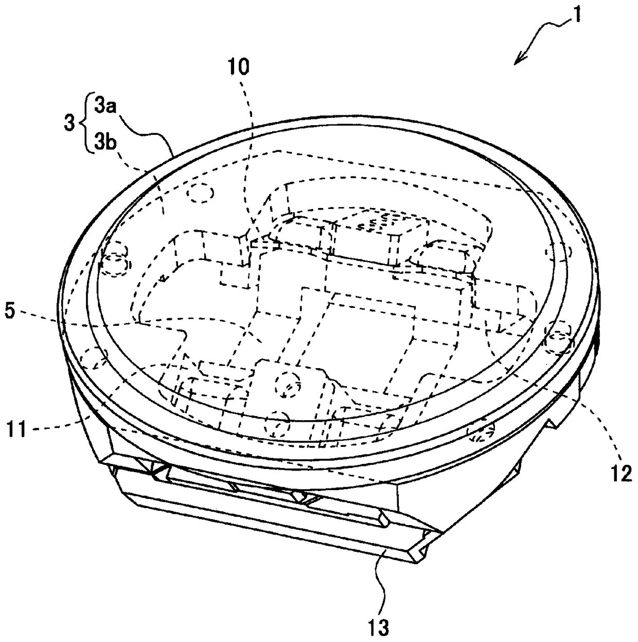
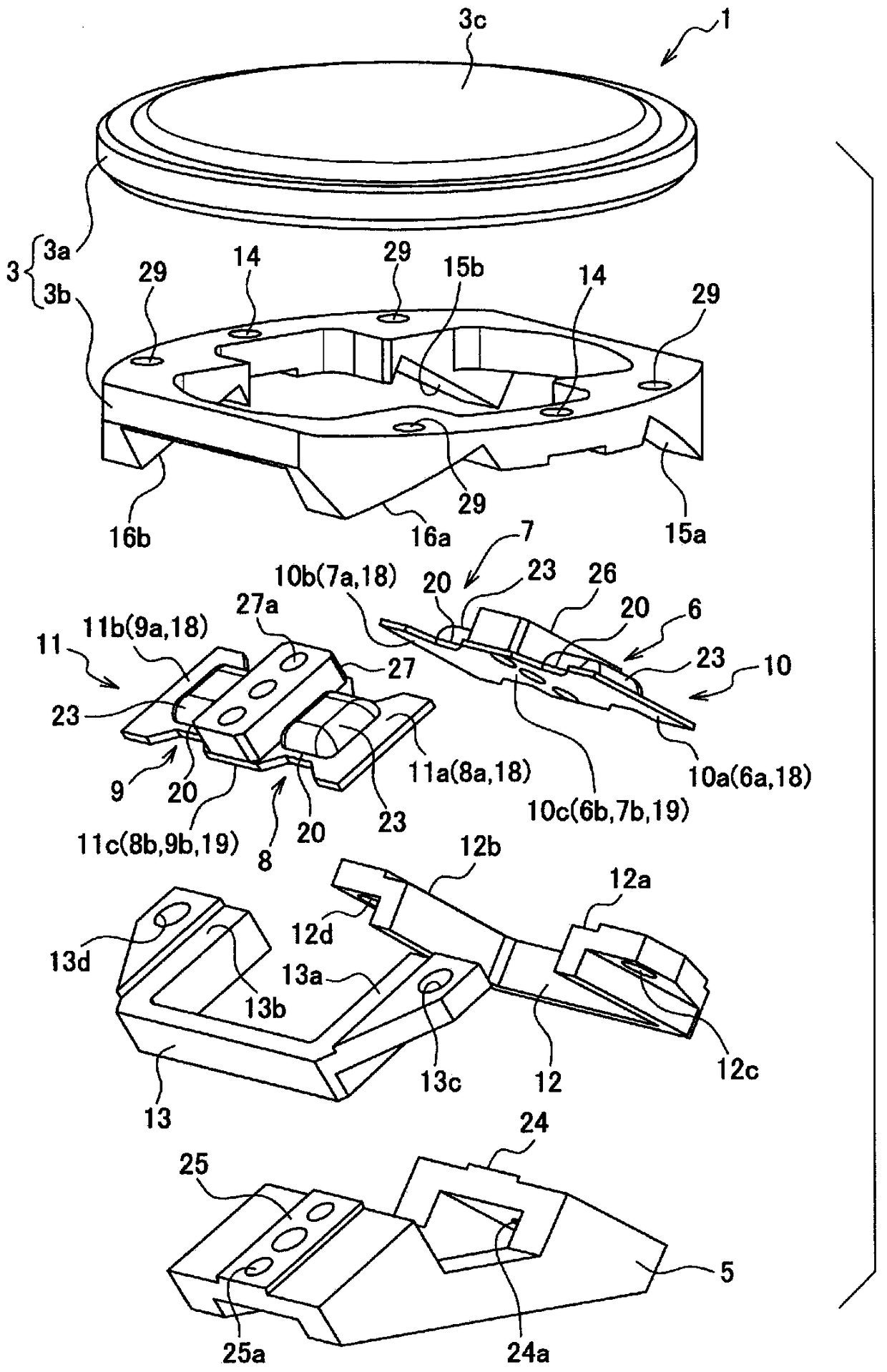
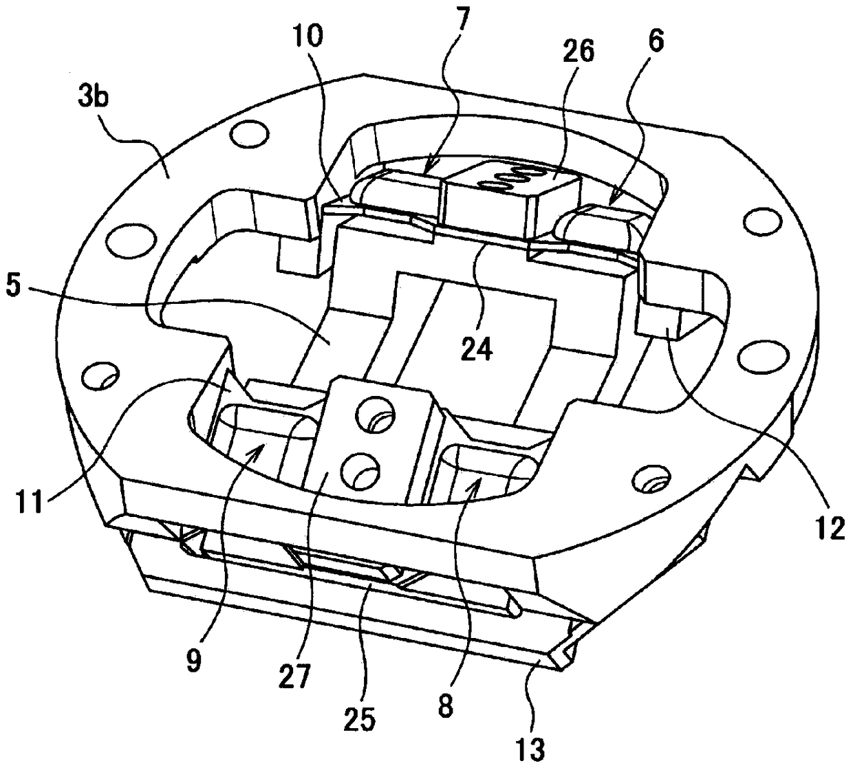
[0040] like Figure 1 to Figure 7 As shown, the operation position detection device 1 of the first embodiment includes: an operation body 3, a base member 5 serving as a base of the device 1, a flat member 10 forming two flat detection bodies 6, 7, and a flat body. The plate members 11 of the two detection bodies 8 and 9 and the pressing members 12 and 13 for connecting the plate members 10 and 11 to the operating body 3 .

[0041] The operating body 3 is composed of a plate-shaped (disk-shaped in this example) operating member 3 a and a substantially cylindrical frame member 3 b. In addition, in the following description, with respect to the up-down direction of the operation position detection device 1 , the side of the operation member 3 a is up, and the side of the base member 5 is down.

[0042] The operation member 3a is attached to the upper side end surface of the frame member 3b via the screw hole 14 provided in the frame member 3b, for example. The circular upper s...


PUM


Abstract

An operation position detection device equipped with: an operation element (3) having an operation surface (3c); a base member (5); four planar detection elements (6-9), each having at one end a connecting part and at the other end a securing part, and having a detection surface (20) between the connecting part and the securing part; a strain detection unit (21) provided on each of the detection surfaces (20); and an operation position calculation unit (31). The detection bodies are arranged by twos at a prescribed angle with respect to the operation surface, such that the extended planes (S1, S2) of the detection surfaces intersect one another at a position between these detection bodies in the planar direction of the operation surface, and such that the distance between the line of intersection (L1) of the extended planes and the operation surface is no greater than a prescribed value.

Description

[0001] This application claims the priority of Japanese application No. 2013-157591 filed on July 30, 2013 and Japanese application No. 2014-24404 filed on February 12, 2014, and the contents thereof are cited here. technical field [0002] The present disclosure relates to an operation position detection device that detects the position of a force acting on an operation surface. Background technique [0003] Patent Document 1 discloses an operation position detection device that detects the position of a force acting on an operation surface. In this operation position detection device, a strain body having a displacement transmission surface deformed according to the operation force generated by pressing the operation surface is provided, a strain detection part is provided on the displacement transmission surface of the strain body, and the The displacement transmission surface is arranged on the same surface as the operation surface. Furthermore, according to this config...

Claims


Application Information

Patent Timeline
Patent Type & Authority Patents(China)
IPC IPC(8): G06F3/041G01B7/16
CPCG06F3/03547G06F3/0338
Inventor 畑中真二伊口整
Owner DENSO CORP
Why Eureka
Try Eureka