Tensile torsion fatigue comprehensive testing machine for rubber materials

A comprehensive test and rubber material technology, which is applied in the field of rubber material fatigue performance detection devices, can solve the problems of inability to provide test environment and test methods, low reliability, large error of performance parameters, etc., and achieve simple structure, convenient use, and measurement The effect of accurate data

Active Publication Date: 2018-07-06
王友善
View PDF10 Cites 0 Cited by
  • Summary
  • Abstract
  • Description
  • Claims
  • Application Information

AI Technical Summary

Problems solved by technology

At present, the fatigue testing machines in the rubber industry are all single-function tensile fatigue testing machines or torsional fatigue testing machines, which can only test the tensile fatigue characteristics or torsional fatigue characteristics of rubber parts alone. In the machinery industry such as transportation, the stress of rubber parts is varied, such as: first stretching and then twisting, first twisting and then stretching, stretching and twisting at the same time and other composite forces, the service life of rubber parts is also There will be large differences due to different operating temperatures
Existing rubber material fatigue testing machines cannot adapt and meet the requirements of the above working conditions, and cannot provide the same test environment and test methods as the real use environment and working methods, and the measured performance parameters have large errors and low reliability

Method used


Image

  • Tensile torsion fatigue comprehensive testing machine for rubber materials
  • Tensile torsion fatigue comprehensive testing machine for rubber materials
  • Tensile torsion fatigue comprehensive testing machine for rubber materials

Examples


Embodiment Construction

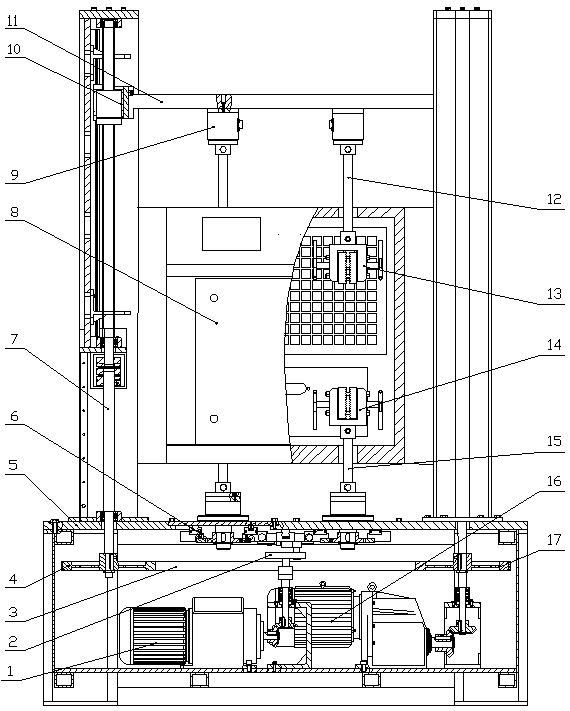
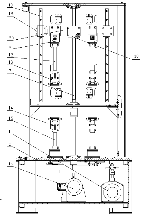
[0017] Such as Figure 1-5 The tensile and torsion fatigue testing machine for rubber materials shown is provided with a mounting bracket 5, a stretching motor 16 and a torsion motor 1 are provided in the lower part of the mounting bracket 5, and at least two parallel lifting guide rails are vertically provided on the mounting frame 5 18. Each lifting guide rail 18 is provided with a lifting slide seat 19, and the two lifting slide seats 19 of each lifting guide rail 18 are provided with an active beam 20. The active beam 20 is provided with an upper chuck, and the mounting bracket 5 is provided with There is a stretching screw, the stretching screw is a ball screw, the screw 7 of the stretching screw is connected to the stretching motor, the nut 10 of the stretching screw is connected to the active beam 20, the stretching motor 16 works, and drives the stretching The screw rod 7 of the lead screw rotates to drive the nut 10 and the active crossbeam 20 to move up and down; the...


PUM


Abstract

A rubber material tensile torsion fatigue comprehensive testing machine, which relates to a rubber material fatigue performance testing device, is provided with a mounting bracket, and a stretching motor, a torsion motor, a lifting guide rail and a stretching screw are arranged in the mounting bracket, and the lifting guide rail is provided with a lifting Sliding seat, there is an active crossbeam between the lifting and lowering slides, an upper clamp is provided on the active crossbeam, the stretching screw is connected with the stretching motor and the active crossbeam, the lower part of the mounting bracket is provided with a transmission shaft, and the upper end of the transmission shaft is provided with a lower clamp There is a torsion drive gear on the lower side of the transmission shaft, and a drive rack that meshes with the torsion drive gear is provided on the side of the torsion drive gear; a crank turntable is provided on the torsion motor, and the crank turntable is hinged with one end of the connecting rod, and the connecting rod is hinged. There is a reciprocating connection block connected with the driving rack; a pull-torsion compound force sensor is arranged between the upper chuck and the active beam. The invention has simple structure and convenient use, can truly simulate the working environment and working mode of the rubber parts, has accurate measurement data, and can truly reflect the actual performance of the parts.

Description

technical field [0001] The invention relates to a device for detecting the fatigue performance of rubber materials, in detail, it is a comprehensive tensile and torsion fatigue testing machine for rubber materials with simple structure and high functions. Background technique [0002] We know that rubber is one of the widely used polymer materials. With the development of industrial economy, the performance requirements of rubber materials are getting higher and higher. Fatigue performance is the basis for studying the life of rubber products. At present, the fatigue testing machines in the rubber industry are all single-function tensile fatigue testing machines or torsional fatigue testing machines, which can only test the tensile fatigue characteristics or torsional fatigue characteristics of rubber parts alone. In the machinery industry such as transportation, the stress of rubber parts is varied, such as: first stretching and then twisting, first twisting and then stret...

Claims


Application Information

Patent Timeline
Patent Type & Authority Patents(China)
IPC IPC(8): G01N3/26G01N3/08
CPCG01N3/08G01N3/26G01N2203/005
Inventor 王友善
Owner 王友善
Why Eureka
Try Eureka