Medical bearing assembly

A technology for components and bearing columns, applied in the direction of lifting devices, lifting frames, etc., can solve the problems of precision thread precision drop, accidental impact, damage and so on

Inactive Publication Date: 2016-04-20
桐乡市佳栋机械设备有限公司
View PDF5 Cites 0 Cited by
  • Summary
  • Abstract
  • Description
  • Claims
  • Application Information

AI Technical Summary

Problems solved by technology

[0004] However, during the use of the bearing assembly, due to the long-term load of the weighing part directly acting on the thread, and some unexpected impacts may occu

Method used


Image

  • Medical bearing assembly
  • Medical bearing assembly
  • Medical bearing assembly

Examples


Embodiment Construction

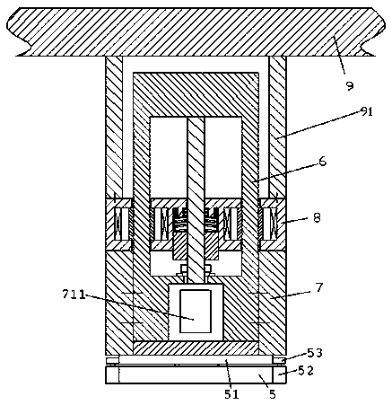
[0012] Combine below Figure 1-3 The present invention will be described in detail.

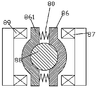
[0013] A medical bearing assembly according to an embodiment, comprising a base frame 7, a guide bearing column part 6 fixedly connected to the base frame 7, a movable bearing part 8, a platform part 9, and connecting the platform part 9 and the movable bearing part 8 A fixed connecting portion 91; wherein, the platform portion 9 is used to carry loads, and the guide bearing column part 6 includes two guide bearing columns 61, 62 arranged symmetrically, each of the guide bearing columns 61, 62 Evenly distributed ring teeth 612 are provided, and the movable load bearing part 8 includes a pair of load clamps arranged bilaterally symmetrically for cooperating with the ring teeth 612 of the two guide bearing columns 61, 62 respectively. The pair of bearing clamps each includes two toothed clamps 86, 861 oppositely arranged, and the two toothed clamps 86, 861 can clamp the corresponding guide be...


PUM


Abstract

A medical bearing assembly comprises a base frame (7), a guiding and bearing column part (6) fixedly connected with the base frame (7), a movable bearing part (8), a platform part (9) and a connecting part (91) through which the platform part (9) and the movable bearing part (8) are fixedly connected, wherein the platform part (9) is used for bearing load; the guiding and bearing column part (6) comprises two symmetrically-arranged guiding and bearing columns (61 and 62), and the guiding and bearing columns (61 and 62) are each provided with evenly-distributed annular teeth (612); the movable bearing part (8) comprises bearing clamping block pairs which are matched with the annular teeth (612) of the two guiding and bearing columns (61 and 62) and symmetrically arranged in a left and right mode.

Description

technical field [0001] The invention relates to the field of medical equipment, in particular to a medical bearing assembly. Background technique [0002] In medical equipment, it is often necessary to precisely adjust the height position of some bearing components, such as some medical detection devices, and the difference in height position will affect the detection results. [0003] Existing position adjustment devices are often implemented with precision threads. These precision threads can realize controlled high-precision mechanical transmission, combined with applications such as sensors and controllers, can achieve precise control of position. [0004] However, during the use of the bearing assembly, due to the long-term load of the weighing part directly acting on the thread, and some unexpected impacts may occur, it is easy to cause the precision of the precision thread to drop and be damaged, thereby shortening the service life of the equipment and increasing ma...

Claims


Application Information

Patent Timeline
IPC IPC(8): B66F7/14B66F7/28
CPCB66F7/14B66F7/28
Inventor 舒泳军
Owner 桐乡市佳栋机械设备有限公司
Why Eureka
Try Eureka