Upright locking mechanism

A locking mechanism and column technology, applied in the direction of pivot connection, etc., can solve the problems of poor positioning accuracy and inconvenient use, and achieve the effect of convenient use

Inactive Publication Date: 2016-04-20
南京威翔科技有限公司
View PDF4 Cites 0 Cited by
  • Summary
  • Abstract
  • Description
  • Claims
  • Application Information

AI Technical Summary

Problems solved by technology

The adjustment and positioning device currently used usually uses a punching buckle or a lock for positioning and locking, which has poor positioning accuracy and is inconvenient to use

Method used


Image

  • Upright locking mechanism
  • Upright locking mechanism

Examples


Embodiment Construction

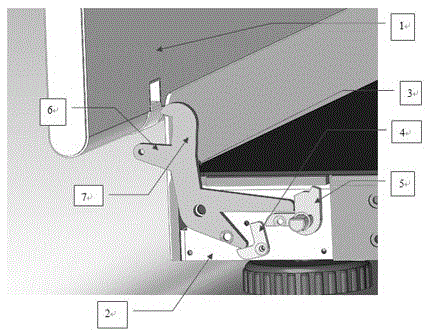
[0008] The present invention is structured as figure 1 As shown, it includes a movable column 1 and a base 2 connected by a rotating shaft, and is characterized in that: the base 2 is connected with a rotary lock hook 3, a rotary pull fork 5 and a reset pull fork 4, and a rotary pull fork 5 Both the reset fork 4 and the reset fork 4 are provided with a reset spring. One end of the rotary lock hook 3 is provided with a bifurcated leg, and the two bifurcated branch legs should not be caught in the twist fork 5 and the reset fork 4, and the other end of the rotary lock hook 3 is the bifurcated lock hook head 7 and the lock The hook foot 6, the movable column 1 is provided with a lock hole corresponding to the position of the lock hook head 7. When the movable column 1 rotates, the lock hook foot 6 is pressed to drive the rotary lock hook 3 to rotate, and the lock hook head 7 is locked into the lock hole.

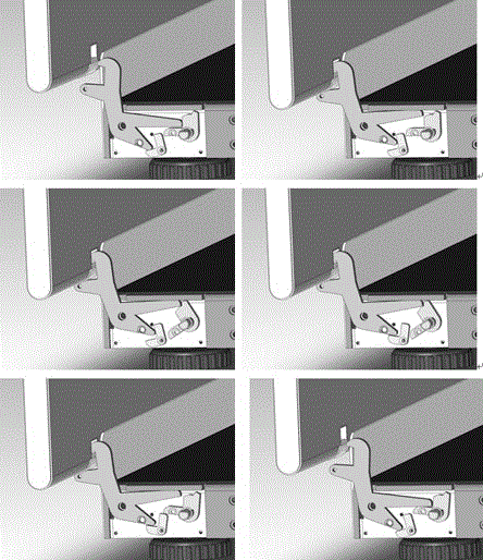
[0009] The working process of the present invention is as figure 2 Shown:

...


PUM


Abstract

The invention provides an upright locking mechanism. The upright locking mechanism comprises a movable upright and a base which are connected via a rotating shaft, wherein a rotary latch hook, a knob shifting fork and a reset shifting fork are connected to the base; a reset spring is arranged on each of the knob shifting fork and the reset shifting fork; branching support legs are formed at one end of the rotary latch hook and the two branching support legs are respectively clamped into the knob shifting fork and the reset shifting fork; a latch hook head and a latch hook support leg which are divergent are formed at the other end of the rotary latch hook; a lock hole corresponding to the latch hook head is formed in the movable upright; the movable upright oppresses the latch hook support leg to drive the rotary latch hook to rotate when rotating; the latch hook head is clamped into the lock hole.

Description

Technical field [0001] The invention relates to the field of mechanical structures, in particular to a column locking mechanism. Background technique [0002] In some devices that need to be rotated, such as seats or doors and windows, the rotation position needs to be positioned. The currently used adjusting and positioning devices usually use punching buckles or locks for positioning and locking, which have poor positioning accuracy and are inconvenient to use. Summary of the invention [0003] In order to solve the problems of the prior art, the present invention provides a column locking mechanism, which can automatically lock the movable components only by operating the movable components, and is convenient to use. [0004] The invention includes a movable column and a base connected by a rotating shaft. The base is connected with a rotating lock hook, a twisting fork and a resetting fork, and both the rotating and the resetting fork are provided with a reset spring. One end ...

Claims


Application Information

Patent Timeline
Patent Type & Authority Applications(China)
IPC IPC(8): F16C11/10
CPCF16C11/10
Inventor 桑明华毛绍斌
Owner 南京威翔科技有限公司
Why Eureka
Try Eureka