Vascular clamp

A technology of vascular clips and clip arms, which is applied in the field of vascular clips, can solve the problems of single locking point, heavy bleeding accidents, and difficulty in making clips, so as to improve the clipping effect, solve the leakage problem, and prevent the locking buckle from slipping off.

Inactive Publication Date: 2016-05-04
徐斌
View PDF8 Cites 8 Cited by
  • Summary
  • Abstract
  • Description
  • Claims
  • Application Information

AI Technical Summary

Problems solved by technology

The clips of these structures have the following disadvantages: 1. The locking point is single. Once slipping occurs, the clip will lose its locking force, which will cause heavy bleeding and serious accidents; 2. The clip relies on flat pressure to flatten blood vessels or pipelines. , so as to achieve the sealing effect, which is prone to leakage; 3. The arms of the clip can only be produced by one-time injection molding, and cannot use a variety of material combinations to meet clinical needs, so the use of absorbable materials is limited
[0003] Clips made of absorbable materials are the direction of clinical needs, but due to the limitations of material properties, it is difficult to make clips like non-absorbable materials

Method used


Image

  • Vascular clamp
  • Vascular clamp
  • Vascular clamp

Examples


Embodiment Construction

[0015] The specific embodiments of the present invention will be further described below in conjunction with the drawings.

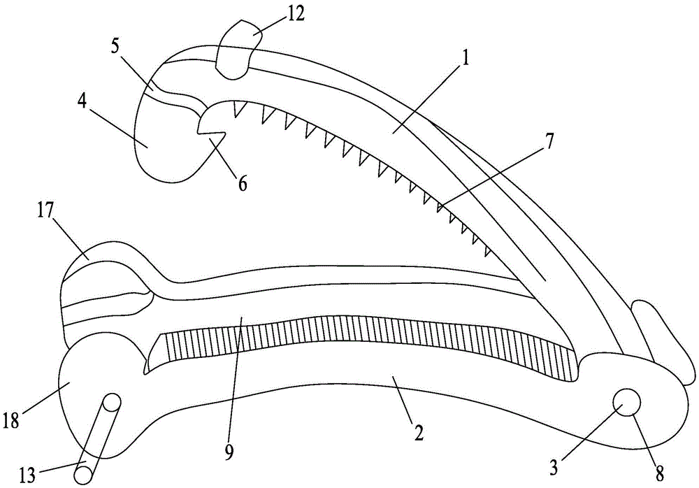
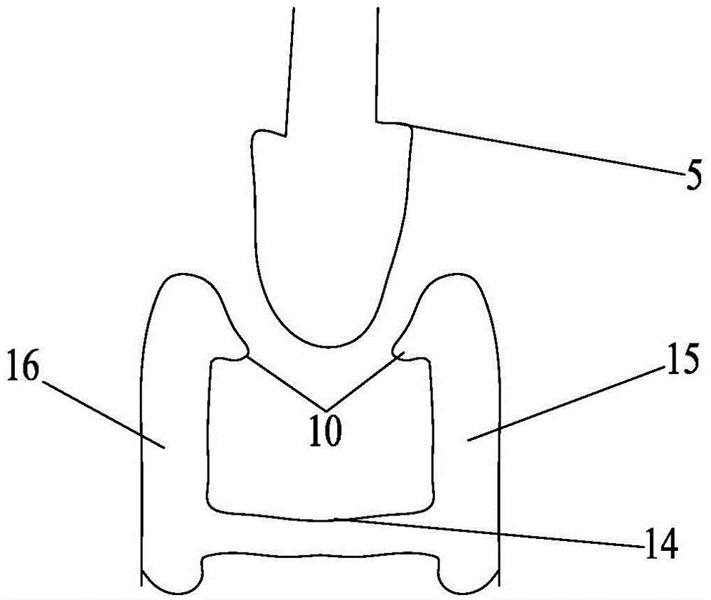
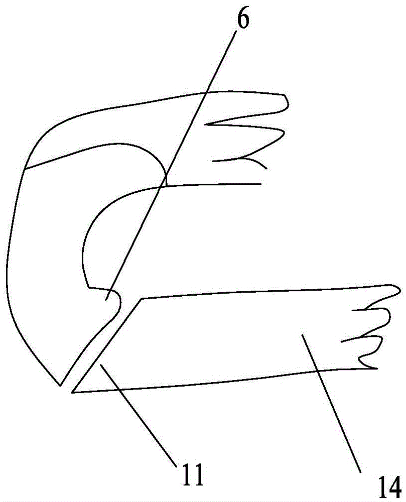
[0016] Figure 1~4 It includes the first clamp arm 1, the second clamp arm 2, the convex shaft 3, the piercing lock head 4, the upper fixed tooth 5, the lower fixed tooth 6, the non-slip tooth 7, the shaft hole 8, the groove 9, the protrusion 10. Groove bottom teeth 11, upper fixing post 12, lower fixing post 13, groove bottom plate 14, groove first elevation 15, groove second elevation 16, second guide seat 17, first guide seat 18, etc.

[0017] Such as Figure 1~4 As shown, the present invention is a vascular clip, which includes a first clip arm 1 and a second clip arm 2. One end of the first clip arm 1 and the second clip arm 2 are hingedly connected, and the second clip arm A groove 9 is opened on the groove 9. The two sides of the front end of the groove 9 respectively form a first guide seat 18 and a second guide seat 17 upwards. Both the first guide...


PUM


Abstract

The invention belongs to the field of medical instruments, and relates to a vascular clamp. The vascular clamp comprises a first clamping arm and a second clamping arm; the end of one side of the first clamping arm and the end of one side of the second clamping arm are hinged, the second clamping arm is provided with a groove, a first guiding seat and a second guiding seat are upwards formed on the two sides of the front end of the groove respectively, and the side, facing the groove, of the first guiding seat and the side, facing the groove, of the second guiding seat are each provided with a protrusion; the locking end of the first clamping arm is bent downwards to form a puncturing lock head, upper fixing teeth are formed at the two ends of the upper portion of the puncturing lock head, and a lower fixing tooth is formed on the inner side of the puncturing lock head; a groove bottom plate is arranged at the bottom of the groove, and a groove bottom tooth is arranged at the front end of the groove bottom plate; after the first clamping arm and the second clamping arm are closed, the lower fixing tooth is locked at the groove bottom tooth, and the upper fixing teeth are clamped under the protrusions. The vascular clamp is reliable and stable in locking.

Description

Technical field [0001] The invention belongs to the field of medical equipment and relates to a blood vessel clamp. Background technique [0002] Similar products commonly used in clinical practice are called vascular clip, ligation clip, ligation vascular clip, etc., which are made of non-absorbable or absorbable biomaterials by one-time injection molding. The clips of these structures have the following disadvantages: 1. The locking point is single, once slipping off, the clip will lose the locking force, which will cause hemorrhage and serious accidents; 2. The clip relies on the flat pressure to flatten the blood vessel or pipe , So as to achieve the effect of sealing, this method is prone to leakage; 3. The clip arms can only be produced by injection molding at one time, and can not use multiple material combinations to meet clinical needs, so the use of absorbable materials is limited. [0003] Clips made of absorbable materials are the direction of clinical demand, but due ...

Claims


Application Information

Patent Timeline
Patent Type & Authority Applications(China)
IPC IPC(8): A61B17/122
CPCA61B17/122
Inventor 徐斌
Owner 徐斌
Why Eureka
Try Eureka