Tension applying component, yarn storage device and yarn rolling apparatus

A yarn and tension technology, which is applied in the field of tension-applying components, can solve the problems of non-tension-applying component weight balance records, large tension fluctuations, and yarn application.

Inactive Publication Date: 2016-05-04
MURATA MASCH LTD
View PDF9 Cites 2 Cited by
  • Summary
  • Abstract
  • Description
  • Claims
  • Application Information

AI Technical Summary

Problems solved by technology

As a result, the tension applying member cannot follow the fluctuation of the yarn with a constant force, so it cannot contact the yarn, and the fluctuation of the tension becomes large.
In addition, there are cases where the yarn is temporarily separated from the tensioning member, skipping occurs, or the yarn is completely separated from the tensioning member.
[0005] In the case of reducing the weight of the tensioning member in order to suppress the inertial force acting on the tensioning member, sufficient force cannot be applied to the yarn, so it is difficult to apply the desired tension to the yarn
[0006] In addition, in Japanese Patent Application Laid-Open No. 2010-180023, there is no description regarding the inertial force acting on the tension applying member and the weight balance of the tension applying member.

Method used


Image

  • Tension applying component, yarn storage device and yarn rolling apparatus
  • Tension applying component, yarn storage device and yarn rolling apparatus
  • Tension applying component, yarn storage device and yarn rolling apparatus

Examples


Embodiment Construction

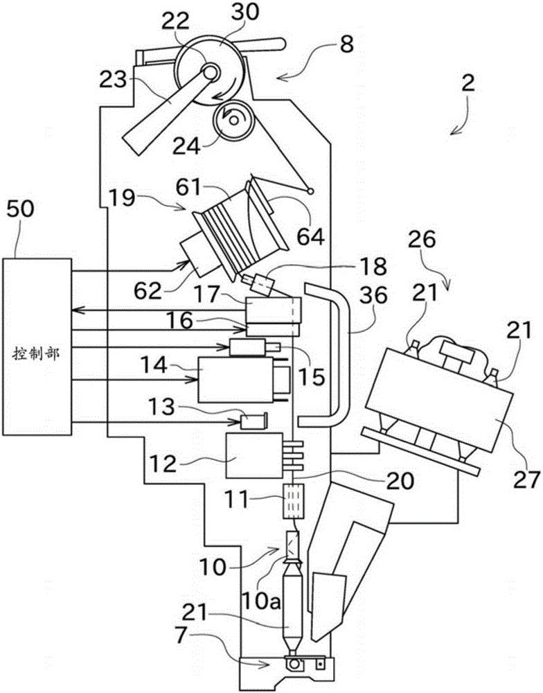
[0042] Next, embodiments of the present invention will be described. First, refer to figure 1 The outline of the automatic winder (yarn winding device) will be described. The automatic winder has a structure in which a plurality of winder units 2 are arranged side by side. In addition, this automatic winder includes an unillustrated machine management device for collectively managing the winder unit 2, and an unillustrated bellows including a compressed air source and a negative pressure source.

[0043] Such as figure 1As shown, the winding unit 2 mainly includes a control unit 50 , a yarn supplying bobbin support unit (yarn supplying unit) 7 , and a winding unit (package forming unit) 8 . The winding unit 2 is configured to unwind the yarn (spun yarn) 20 supported on the yarn supplying bobbin 21 supported by the yarn supplying bobbin support portion 7 and to wind it back into the package 30 . Note that, in the following description, the upstream side and the downstream s...


PUM


Abstract

The invention relates to a tension applying apparatus, a yarn storage device and a yarn rolling apparatus. Tension can be properly applied to yarns even when yarns are lead out of a retention body of residual yarns at high speed. An automatic winder is equipped with a feeding cylinder pipe supporting part, a yarn storage device and a rolling part. The yarn storage device has a retention roller and a tension applying component (64). The tension applying component (64) can be installed on the retention roller in a rotating way and equipped with a balance weight (73) to enable a gravity center to be closer to the rotating shaft side than the center in a length direction; tension can be applied when the tension applying component has a contact with yarns lead out of the retention roller. At least the density or weight of the balance weight (73) is larger than the rest parts of the tension applying component except the balance weight (73).

Description

technical field [0001] The present invention mainly relates to a tension applying member for applying tension to a yarn unwound from a storage body of the stored yarn. Background technique [0002] Conventionally, in yarn winding devices such as automatic winders and textile machines, there are known yarn storage devices that wind yarns around rotating storage rollers, and that provide tension to the yarn drawn out from the yarn storage devices. Tension is imparted to the structure of the part. Japanese Patent Application Laid-Open No. 2010-180023 discloses such a yarn winding device. [0003] The yarn storage device disclosed in JP 2010-180023 A includes a thread taker and an arm. The thread taker contacts the yarn to apply tension to the yarn. The arm part fixes the thread body and is installed on the yarn storage device via the flyer shaft. In addition, an elastic member is arranged inside the arm. [0004] As the speed at which the yarn is pulled out from the yarn s...

Claims


Application Information

Patent Timeline
IPC IPC(8): B65H59/00
Inventor 蛭川正夫
Owner MURATA MASCH LTD
Why Eureka
Try Eureka