Connector shell and connector

A connector and housing technology, applied in the field of connector housings and connectors, can solve problems such as over-insertion of contacts, and achieve the effect of avoiding over-insertion and convenient use.

Active Publication Date: 2018-01-09
CHINA AVIATION OPTICAL-ELECTRICAL TECH CO LTD
View PDF5 Cites 2 Cited by
  • Summary
  • Abstract
  • Description
  • Claims
  • Application Information

AI Technical Summary

Problems solved by technology

[0005] The object of the present invention is to provide a connector housing that does not require the contacts to be mated and retracted during the locking connection, so as to solve the problem of over-insertion of the contacts when the existing connector adopts curved groove connection and locking; at the same time , the present invention also provides a connector using the housing

Method used


Image

  • Connector shell and connector
  • Connector shell and connector
  • Connector shell and connector

Examples


Embodiment 1

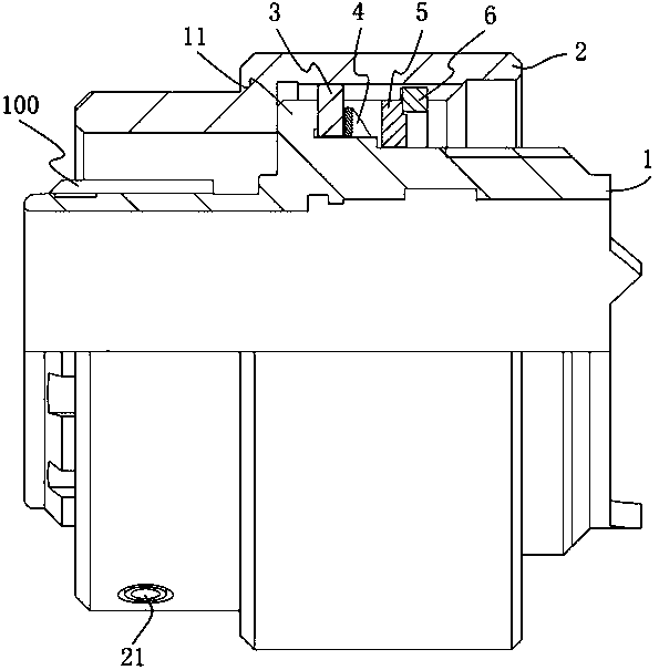
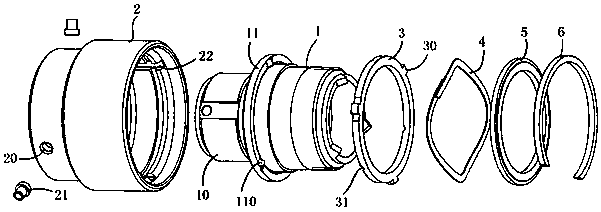
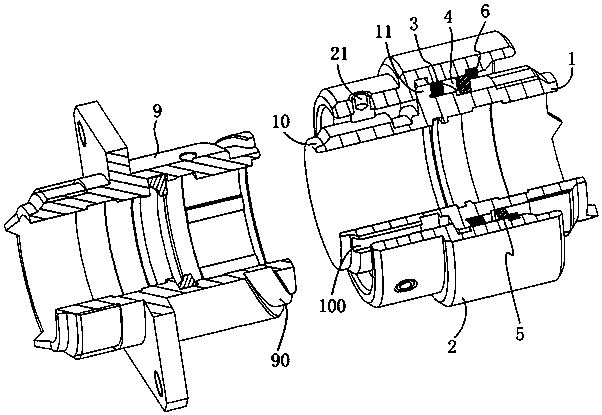
[0019] Embodiment 1 of the connector of the present invention includes a connector housing and a contact piece disposed in the housing. Among them, the structure of the connector housing is as follows Figure 1-2 As shown, it includes an outer shell 1 whose axis extends forward and backward, and a connecting nut 2 that is rotatably sleeved on the outer shell 1 and is used to lock and connect with the mating connector shell through a curved groove staple structure. The connector shell 1 The front end is the plug end 10. In this embodiment, the front end of the connecting nut 2 is provided with a staple installation hole 20, and a staple 21 is installed in the staple installation hole 20. Correspondingly, the housing of the adapter connector is provided with a groove. Certainly, in other embodiments, curved grooves may be provided on the connecting nut, and correspondingly, the staples may be provided on the insertion end of the housing of the mating connector.

[0020] The o...

Embodiment 3

[0025] Embodiment 3 of the connector of the present invention: the difference from Embodiment 1 is that there are two axial protrusions on the stopper ring, and correspondingly, there are two axial protrusions on the locking ring. At this time, the central angle corresponding to the single curved groove on the mating connector housing is 180°.

[0026] Embodiment 4 of the connector of the present invention: the difference from Embodiment 1 is that there are six axial protrusions on the stopper ring, and correspondingly, there are six axial protrusions on the locking ring. At this time, the central angle corresponding to the single curved groove on the mating connector housing is 60°.

[0027] Embodiment 5 of the connector of the present invention: the difference from Embodiment 1 is that the rear side of the connecting nut is provided with an inturned edge, and the retaining ring is located on the front side of the inverted edge and stops with the front side of the inverted ed...


PUM


Abstract

The invention provides a connector shell and a connector. The connector shell comprises a shell body of which the axis extends front and back, and a connecting nut sleeving the shell body in a rotating way and used for getting connection with an adapted connector shell in a locking way through a curved groove-clamp structure; a stopper bulge ring is arranged at the periphery of the shell body; one or more than two axial bulges are arranged axially at intervals on the rear side of the stopper bulge ring; a locking ring stopping rotation in circumferential direction relative to the connecting nut is arranged behind the stopper bulge ring on the shell body in a sleeving way; the front side of the locking ring is provided with axial grooves matched with the axial bulges and in one-to-one correspondence with the axial bulges in quantity; the rear side of the locking ring is provided with a spring used for providing a forward elastic force to the locking ring. The connector shell provided by the invention is simple in structure, can avoid over plugging of contacts during use, is convenient to use and has obvious in-place hand feeling.

Description

technical field [0001] The invention relates to a connector housing and a connector. Background technique [0002] Connectors are components that realize electrical or optical interconnection. Common circular connectors have a variety of connection methods, such as threaded connections, bayonet connections, push-pull connections, etc. The shell of the connector mainly plays the role of sealing, protecting, guiding and locking the connection. [0003] For example, the Chinese invention patent with the authorized announcement number of CN101707312B and the authorized announcement date of 2012.01.25 discloses a threaded connection connector. The outer side of the plug housing of this threaded connection connector is rotatably equipped with a connecting nut with internal threads. The inserting end of the connecting nut is provided with a staple, and the inserting end of the socket housing is provided with a spiral groove matched with the staple, thereby forming a curved groove ...

Claims


Application Information

Patent Timeline
Patent Type & Authority Patents(China)
IPC IPC(8): H01R13/622H01R13/625H01R13/46G02B6/38
CPCG02B6/3821G02B6/3825G02B6/3831H01R13/46H01R13/622H01R13/625
Inventor 郑文杰周国奇谢亚军
Owner CHINA AVIATION OPTICAL-ELECTRICAL TECH CO LTD
Why Eureka
Try Eureka