Self-locating die plate of sand mold

A self-positioning and template technology, applied in the field of sand casting, can solve problems such as unsatisfactory positioning effect, excessive positioning deviation of upper and lower molds, poor positioning accuracy, etc., and achieve the effect of reducing fire-running phenomenon, reducing the amount of wrong shape, and simple structure

Active Publication Date: 2016-06-01
山东汇金股份有限公司
View PDF6 Cites 3 Cited by
  • Summary
  • Abstract
  • Description
  • Claims
  • Application Information

AI Technical Summary

Problems solved by technology

Poor manufacturing accuracy of positioning components or long-term wear can lead to excessive positioning deviation of the upper and lower molds and wrong castings, which can seriously lead to waste products
[0003] In most cases, the parting surface is flat. For single-sided templates, positioning pins and holes are generally used to meet the requirements. The positioning accuracy is getting worse and worse due to the influence of manufacturing methods, precision and wear; double-sided templates generally do not have positioning pins and holes. , the upper and lower molding is generally carried out at the same time, and the positioning of the upper and lower shapes is generally guaranteed by the accuracy of the molding equipment. With the increase of wear and the collision of the moving vehicle, it may cause wrong shape
Although some templates are divided into curved surfaces, they are designed only because of the need for shape division, not from the perspective of surface positioning, and the positioning effect is not ideal.
Some products have strict requirements on right and wrong type, especially for products that need to be dynamically balanced, such as the differential case of auto parts. The templates mentioned above cannot meet the requirements, especially after the equipment or templates are aging.

Method used


Image

  • Self-locating die plate of sand mold
  • Self-locating die plate of sand mold
  • Self-locating die plate of sand mold

Examples


Embodiment 1

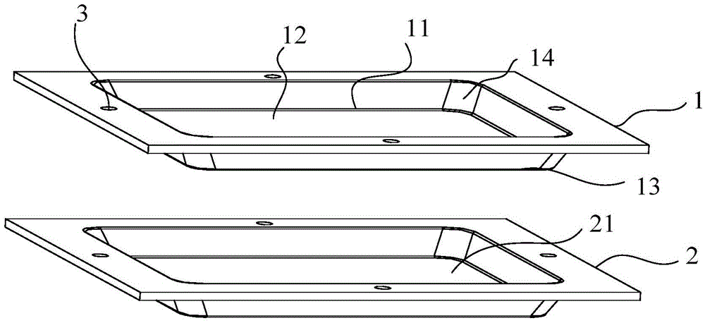
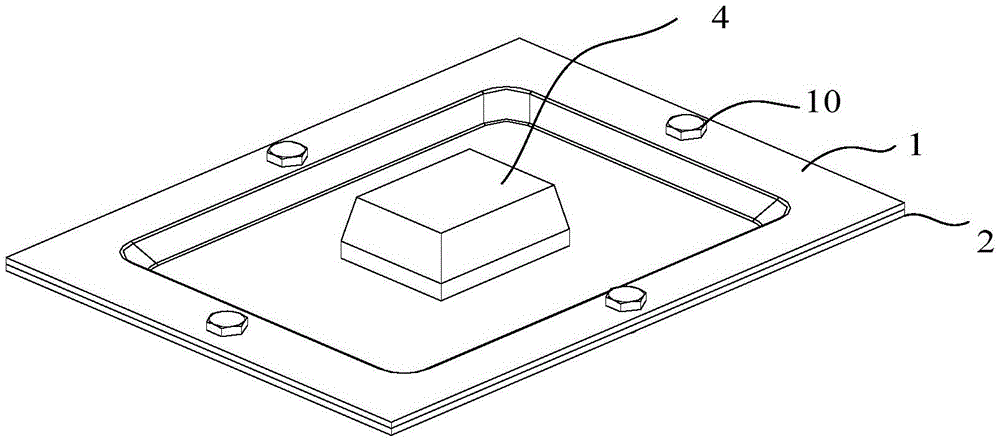
[0028] Example 1, such as figure 1 and figure 2 As shown, the present invention has designed a kind of self-positioning formwork of sand mold, comprises upper formwork 1 and lower formwork 2, the middle part of one side of upper formwork 1 is provided with the concave trapezoidal groove 12 that is concave downward, and the middle part of the other side is provided with The downward convex trapezoidal groove 13, the concave trapezoidal groove 12 and the convex trapezoidal groove 13 form the first trapezoidal groove, and the second trapezoidal groove 21 with the same structure as the first trapezoidal groove is arranged in the middle of the lower template 2. The upper formwork 1 and the lower formwork 2 are clamping positions realized by using the structure of the trapezoidal groove respectively, and the upper and lower formwork 2 cannot move left and right, forward and backward, but can only move up and down; in the first trapezoidal groove 11 The middle part is provided with...

Embodiment 2

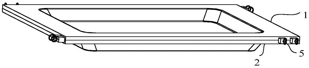
[0030] Embodiment 2, in order to make the positioning of the present invention more accurate and more practical, such as figure 2 As shown, the shape of the upper template 1 is a cuboid, and the first bolt holes 3 are arranged on the outside of the first trapezoidal groove 11 on the upper template 1 of the cuboid shape, and the first bolt holes 3 are at least 4. The lower template 2 The second bolt hole 3 that cooperates with the upper formwork 1 is also arranged on the top, and trapezoidal grooves have been designed on the upper and lower formworks 2 according to the present invention, so that the upper and lower formworks 2 cannot move back and forth, left and right. The first bolt hole 3 and the second bolt hole 3 are respectively set on the 2, and the fixing bolts used to connect the upper and lower formwork 2 are arranged in the two bolt holes 3, and the number of the bolt holes 3 is at least 4, and its function One is fixedly connecting the upper and lower templates 2 s...


PUM


Abstract

The invention belongs to the field of sand mold casting, and relates to a sand mold casting die plate, in particular to a self-locating die plate of a sand mold. The self-locating die plate of the sand mold comprises an upper die plate body and a lower die plate body arranged on the lower portion of the upper die plate body. First trapezoidal grooves are formed in the middle of the upper die plate body. Second trapezoidal grooves are formed in the middle of the lower die plate body. The first trapezoidal grooves are the same as the second trapezoidal grooves in size and structure. Upper mold bags protruding upwards are arranged in the middles of the first trapezoidal grooves. Lower mold bags which are recessed downwards and matched with the upper mold bags are arranged in the middles of the second trapezoidal grooves. Each trapezoidal groove is an isosceles trapezoid, and the locating inclination angle of each isosceles trapezoid ranges from 5 degrees to 40 degrees. The self-locating die plate of the sand mold has the beneficial effects of being simple in structure, precise in location, high in practicability, easy to manufacture and the like, the length of the mold thickness is increased after flat parting is transformed into curved surface parting, and the phenomenon of bleeding from parting is reduced.

Description

technical field [0001] The invention belongs to the field of sand casting, and relates to a sand casting template, in particular to a sand mold self-positioning template. Background technique [0002] There are double-sided templates and single-sided templates for horizontal parting templates. They are generally composed of mold bottom plates, patterns, gating system molds, heating elements, positioning elements, etc. The positioning elements generally refer to positioning pins and sleeves. Poor manufacturing accuracy of positioning components or long-term wear can lead to excessive positioning deviation of the upper and lower molds and wrong castings, which can seriously lead to waste products. [0003] In most cases, the parting surface is flat. For single-sided templates, positioning pins and holes are generally used to meet the requirements. The positioning accuracy is getting worse and worse due to the influence of manufacturing methods, precision and wear; double-side...

Claims


Application Information

Patent Timeline
Patent Type & Authority Applications(China)
IPC IPC(8): B22C7/04
CPCB22C7/005B22C7/04
Inventor 孔庆柱许文青吕海峰
Owner 山东汇金股份有限公司
Why Eureka
Try Eureka