Shoe rack facilitating changing shoes
A technology of shoe rack and left side plate, which is applied in the field of shoe rack, can solve the problems of not being able to sit on people, non-slip shoe rack, inconvenient changing of shoes, etc., and achieve the effect of easy changing of shoes
Inactive Publication Date: 2016-06-08
JIANGYIN SHENGDA BUILDING MATERIALS
View PDF0 Cites 0 Cited by
- Summary
- Abstract
- Description
- Claims
- Application Information
AI Technical Summary
Problems solved by technology
[0002] Shoe rack is a tool used to facilitate people to place shoes that are not worn. Ordinary shoe racks are composed of brackets and beams. Since such shoe racks cannot sit on the top, it is inconvenient for people to change shoes. At the same time, the shoe rack is not slippery and meets Can't meet people's needs
Method used
View moreImage
Smart ImageViewing Examples

Examples
Embodiment Construction
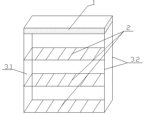
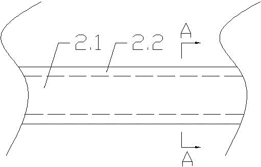
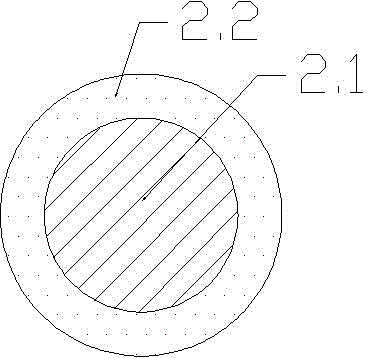
[0018] see Figure 1-3 , the present invention relates to a kind of shoe rack that is convenient for changing shoes, it comprises baffle plate 1, shoe rack 2, left side plate 3.1 and right side plate 3.2, and the top of described left side plate 3.1 and right side plate 3.2 is provided with cushion 1 A plurality of shoe racks 2 are evenly arranged between the left side plate 3.1 and the right side plate 3.2, and the shoe racks 2 include a plurality of rods 2.1 arranged in parallel, and rubber sleeves 2.2 are sheathed on the rods 2.1.
Login to View More PUM
 Abstract
The invention relates to a shoe rack, in particular to a shoe rack facilitating changing shoes. The shoe rack includes a baffle plate (1), shoe holders (2), a left side plate (3.1) and a right side plate (3.2); the top ends of the left side plate (3.1) and the right side plate (3.2) are provided with a seat pad (1); a plurality of shoe holders (2) are evenly arranged between the left side plate (3.1) and the right side plate (3.2); the shoe holders (2) includes a plurality of rods (2.1) which are arranged in parallel; and the rods (2.1) are sleeved with rubber sleeves (2.2). According to the shoe rack facilitating changing shoes, the top ends of the left side plate and the right side plate are provided with the seat pad, and a man can sit on the seat pad and can conveniently change the shoes; and meanwhile, the rods of the shoe rack are sleeved with the rubber sleeves which can effectively prevent slip of the shoes on the shoe rack, and the requirements of people can be met.
Description
technical field [0001] The invention relates to a shoe rack, which belongs to the technical field of daily necessities. Background technique [0002] Shoe rack is a tool used to facilitate people to place shoes that are not worn. Ordinary shoe racks are composed of brackets and beams. Since such shoe racks cannot sit on the top, it is inconvenient for people to change shoes. At the same time, the shoe rack is not slippery and meets Can't meet people's needs. Contents of the invention [0003] The object of the present invention is to overcome above-mentioned deficiency, provides a kind of shoe rack that is convenient for changing shoes. [0004] The purpose of the present invention is achieved like this: [0005] A shoe rack convenient for changing shoes, which includes a baffle plate, a shoe rack, a left side plate and a right side plate, the tops of the left side plate and the right side plate are provided with cushions, and the space between the left side plate and th...
Claims
Login to View More Application Information
Patent Timeline
 IPC IPC(8): A47B61/04
Inventor 钦建华
Owner JIANGYIN SHENGDA BUILDING MATERIALS