a thermostatic faucet

A thermostatic faucet and a pair of technology, applied in the field of thermostatic faucets, can solve the problems of limited use and inability to meet the preferences of different users, and achieve the effects of improving the sealing effect, eliminating water leakage, and having a wide range of applications

Active Publication Date: 2017-12-22
NINGBO CILI CONSTANT TEMPERATURE TECH CO LTD
View PDF8 Cites 0 Cited by
  • Summary
  • Abstract
  • Description
  • Claims
  • Application Information

AI Technical Summary

Problems solved by technology

[0002] The thermostatic faucets currently in use include a shell, a shell fixed in the shell, and a pair of water inlet bends that pass through the back of the shell and communicate with the shell. The shell includes a hot water inlet pipe, a cold water inlet pipeline and a mixing pipeline connected with the hot water inlet pipeline and the cold water inlet pipeline, and a pair of water inlet elbows are respectively connected with the hot water inlet pipeline and the cold water inlet pipeline. The spool is connected with the temperature adjustment handwheel located on the shell. Generally, one or two corresponding water outlets are set on the mixing pipe. When there are two water outlets, the two water outlets are realized through the water diversion valve, and one of the water outlets is independent. Water outlet, this kind of thermostatic faucet is usually connected to a shower or top spray, or connected to the shower and top spray at the same time, but when in use, only the shower or top spray can discharge water, and the use is often limited, which cannot meet the preferences of different users

Method used


Image

  • a thermostatic faucet
  • a thermostatic faucet
  • a thermostatic faucet

Examples


Embodiment 1

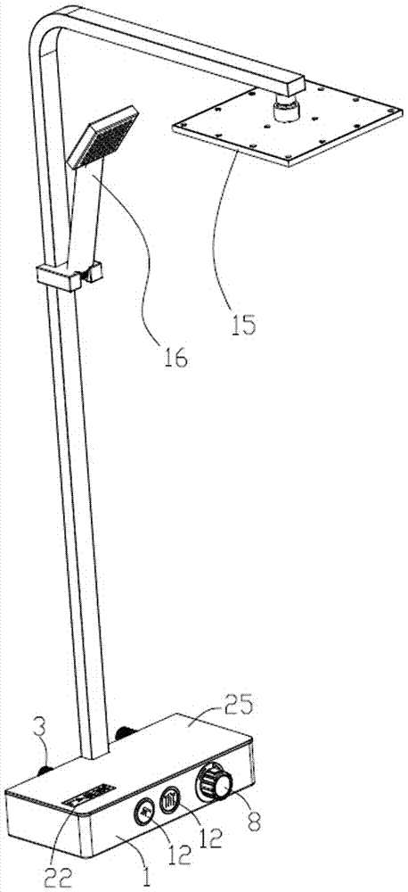
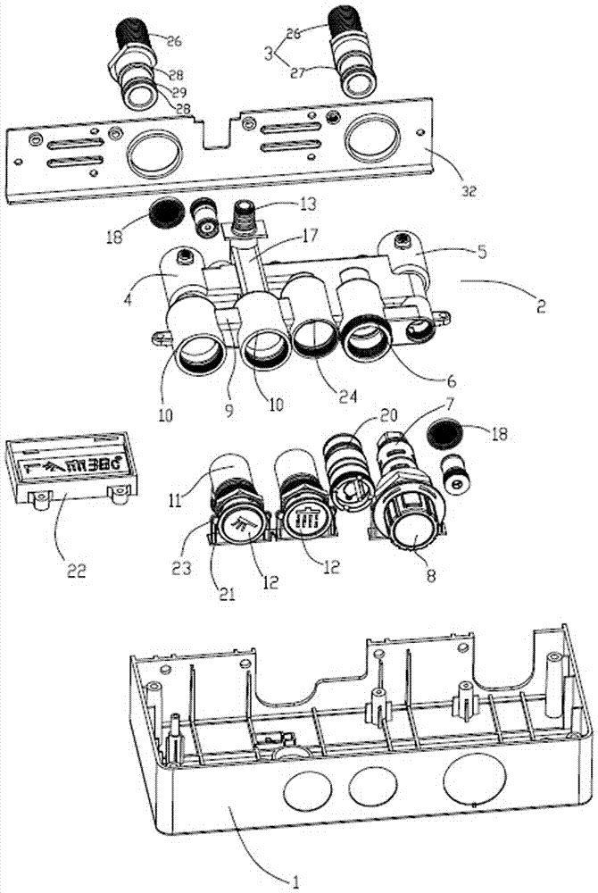
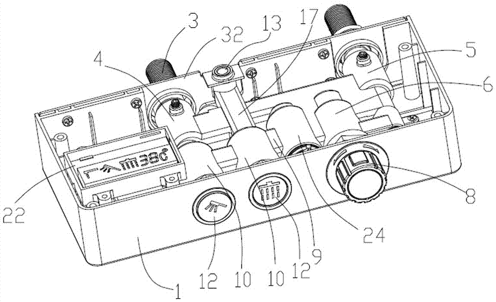
[0024] Such as Figure 1-5 As shown, a thermostatic faucet provided by the present invention includes a casing 1, a casing 2 fixed inside the casing, and a pair of water inlet elbows 3 that pass through the rear side of the casing and communicate with the casing. The casing includes The hot water inlet pipe 4, the cold water inlet pipe 5 and the mixing pipe 6 connected with the hot water inlet pipe and the cold water inlet pipe, and a pair of water inlet bends are respectively connected with the hot water inlet pipe and the cold water inlet pipe The mixing pipe is equipped with a thermostatic valve core 7, which is connected with the temperature adjustment handwheel 8 located on the shell, and the water outlet of the mixing pipe is connected with a mixed water outlet pipe 9, and there are several holes on the mixed water outlet pipe. The connected switch tubes 10 are each provided with a water outlet port, each switch tube is fixed with a switch valve 11, and the switch valves...

Embodiment 2

[0038] Such as Figure 4 , 6 , 7, the difference between this embodiment and embodiment 1 is that there are three switch tubes in this embodiment, that is, there are three water outlets and switch buttons, and a side water outlet is added on the basis of embodiment 1. 33. The side water outlet interface is connected with a bubbler 34, and the bubbler is facing the side water outlet 35 on the front side of the casing so that water can be discharged from the side water outlet.

[0039] In this embodiment, the side water outlet port is located at the end away from the mixing pipe, and the on-off valve corresponding to the side water outlet port can be opened only after the switch valves corresponding to the upper water outlet port and the lower water outlet port are opened, and the water outlet methods are more diverse.


PUM


Abstract

A constant temperature faucet comprises a casing, a casing body fixedly arranged in the casing and a pair of water inlet bent feet which penetrates the rear side of the casing and is communicated with the casing body. The casing body comprises a hot water inlet pipeline, a cold water inlet pipeline and a mixing pipeline communicated with the hot water inlet pipeline and the cold water inlet pipeline. The pair of water inlet bent feet is communicated with the hot water inlet pipeline and the cold water inlet pipeline respectively, a water outlet of the mixing pipeline is connected with a mixed water outlet pipeline which is provided with a plurality of water outlet ports, the mixed water outlet pipeline corresponding to the water outlet ports is provided with switching valves, and the switching valves are in one-to-one correspondence connection with switch buttons arranged on the casing. Through the water outlet ports and the switching valves corresponding to the water outlet ports, the water outlet ports can be connected with different water outlet devices, different water outlet modes can be achieved, so as to meet different users' using hobbies.

Description

technical field [0001] The invention relates to a constant temperature faucet. Background technique [0002] The thermostatic faucets currently in use include a shell, a shell fixed in the shell, and a pair of water inlet bends that pass through the back of the shell and communicate with the shell. The shell includes a hot water inlet pipe, a cold water inlet pipeline and a mixing pipeline connected with the hot water inlet pipeline and the cold water inlet pipeline, and a pair of water inlet elbows are respectively connected with the hot water inlet pipeline and the cold water inlet pipeline. The spool is connected with the temperature adjustment handwheel located on the shell. Generally, one or two corresponding water outlets are set on the mixing pipe. When there are two water outlets, the two water outlets are realized through the water diversion valve, and one of the water outlets is independent. Water outlet, this kind of thermostatic faucet is usually connected to a ...

Claims


Application Information

Patent Timeline
Patent Type & Authority Patents(China)
IPC IPC(8): F16K11/20F16K37/00E03C1/042
CPCE03C1/042F16K11/20F16K37/0025
Inventor 卢于波
Owner NINGBO CILI CONSTANT TEMPERATURE TECH CO LTD
Why Eureka
Try Eureka