Fiber connector adjustable square wave tester

An optical fiber connector and tester technology, applied in the direction of testing optical performance, etc., can solve the problems of difficult to effectively meet the needs of practical application of optical fiber connectors, difficult installation and positioning, low work efficiency, etc., to achieve efficient and convenient conduction efficiency and Stability, simple structure, flexible and convenient use

Inactive Publication Date: 2016-06-15
SUZHOU JIALAN ZHIYUAN ELECTRONICS TECH CO LTD
View PDF7 Cites 1 Cited by
  • Summary
  • Abstract
  • Description
  • Claims
  • Application Information

AI Technical Summary

Problems solved by technology

[0002] In the quality inspection of optical fiber connectors, it is an important link to detect the conduction ability of optical fiber connectors to optical signals through adjustable square wave signals. The connector is connected with an adjustable square wave tester, and the optical fiber connector is tested by the adjustable square wave tester. Although this method can meet the needs of testing, it is difficult to install and locate because of the small size of the optical fiber connector. Larger, which leads to relatively low work efficiency for the adjustable square wave test, and the operation is more complicated, it is difficult to effectively meet the needs of the practical application of the optical fiber connector. Therefore, in view of this phenomenon, it is urgent to develop an adjustable optical fiber connector. Square wave detection equipment to meet the needs of actual production use

Method used


Image

  • Fiber connector adjustable square wave tester

Examples


Embodiment Construction

[0014] In order to make the technical means, creative features, goals and effects achieved by the present invention easy to understand, the present invention will be further described below in conjunction with specific embodiments.

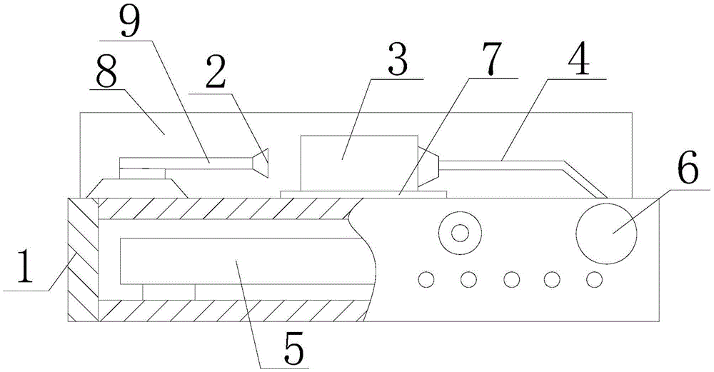
[0015] Such as figure 1 The adjustable square wave tester for an optical fiber connector includes a protective housing 1, a detection light source 2, an optical fiber connector positioning buckle 3, a test pigtail 4, an adjustable square wave test device 5 and an optical power meter 6. The protective shell 1 is a closed cavity structure, and the adjustable square wave test device 5 is embedded in the protective shell 1. The detection light source 2 and the positioning buckle 4 of the optical fiber connector are installed on the upper surface of the protective shell 1, and the detection The light source 2 and the positioning buckle 3 of the optical fiber connector are coaxially distributed, and the positioning buckle 3 of the optical fiber connecto...


PUM


Abstract

The invention relates to an adjustable square wave tester for optical fiber connectors, which includes a protective shell, a detection light source, an optical fiber connector positioning buckle, a test pigtail, an adjustable square wave test device and an optical power meter. The protective shell is Closed cavity structure, adjustable square wave test device embedded in the protective shell, the detection light source and the positioning buckle of the optical fiber connector are installed on the upper end surface of the protective shell, and the detection light source and the positioning buckle of the optical fiber connector are distributed coaxially, and the optical fiber The connector positioning buckle communicates with the adjustable square wave test device through the test pigtail, and the optical power meter is embedded in the side surface of the protective case and communicates with the adjustable square wave test device through the test pigtail. The invention can efficiently and conveniently carry out conduction efficiency and stability of the optical signal on the optical fiber connector, thereby helping to improve the qualified rate of the optical fiber connector product, and helping to reduce the labor intensity and cost of the optical fiber connector detection operation .

Description

technical field [0001] The invention relates to a testing device for an optical fiber connector, in particular to an adjustable square wave tester for an optical fiber connector. Background technique [0002] In the quality inspection of optical fiber connectors, it is an important link to detect the conduction ability of optical fiber connectors to optical signals through adjustable square wave signals. The connector is connected with an adjustable square wave tester, and the optical fiber connector is tested by the adjustable square wave tester. Although this method can meet the needs of testing, it is difficult to install and locate because of the small size of the optical fiber connector. Larger, which leads to relatively low work efficiency for the adjustable square wave test, and the operation is more complicated, and it is difficult to effectively meet the needs of the practical application of the optical fiber connector. Therefore, in view of this phenomenon, it is u...

Claims


Application Information

Patent Timeline
IPC IPC(8): G01M11/02
CPCG01M11/02
Inventor 虢杰毕延文余新文谢巷松
Owner SUZHOU JIALAN ZHIYUAN ELECTRONICS TECH CO LTD
Why Eureka
Try Eureka