Signal generator with frequency sweeping function

A signal generator and frequency sweep technology, applied in the field of testing and measurement, can solve the problems of single frequency sweep function, affecting the output waveform diversity of the frequency sweep function, and unable to meet the actual needs of users, and achieve the effect of expanding the frequency sweep function.

Active Publication Date: 2016-06-15
SUZHOU RIGOL PRECISION ELECTRIC TECH
View PDF5 Cites 3 Cited by
  • Summary
  • Abstract
  • Description
  • Claims
  • Application Information

AI Technical Summary

Problems solved by technology

However, there are also disadvantages: the frequency sweep function is single, and the sweep types within the sweep time t1 and the return time t3 must be consistent. This limitation affects the diversity of the output waveforms of the frequency sweep function, which cannot meet the actual needs of users.

Method used


Image

  • Signal generator with frequency sweeping function
  • Signal generator with frequency sweeping function
  • Signal generator with frequency sweeping function

Examples


Embodiment Construction

[0054] In order to make the above objects, features and advantages of the present invention more comprehensible, the present invention will be further described in detail below in conjunction with the accompanying drawings and specific embodiments.

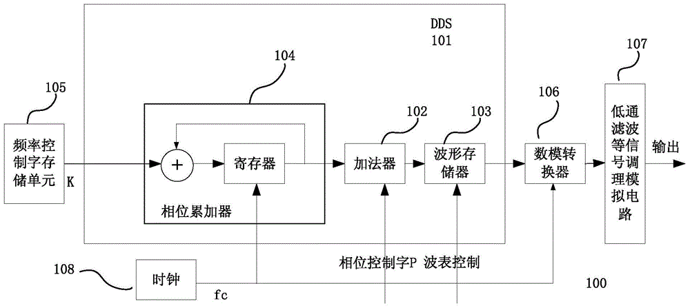
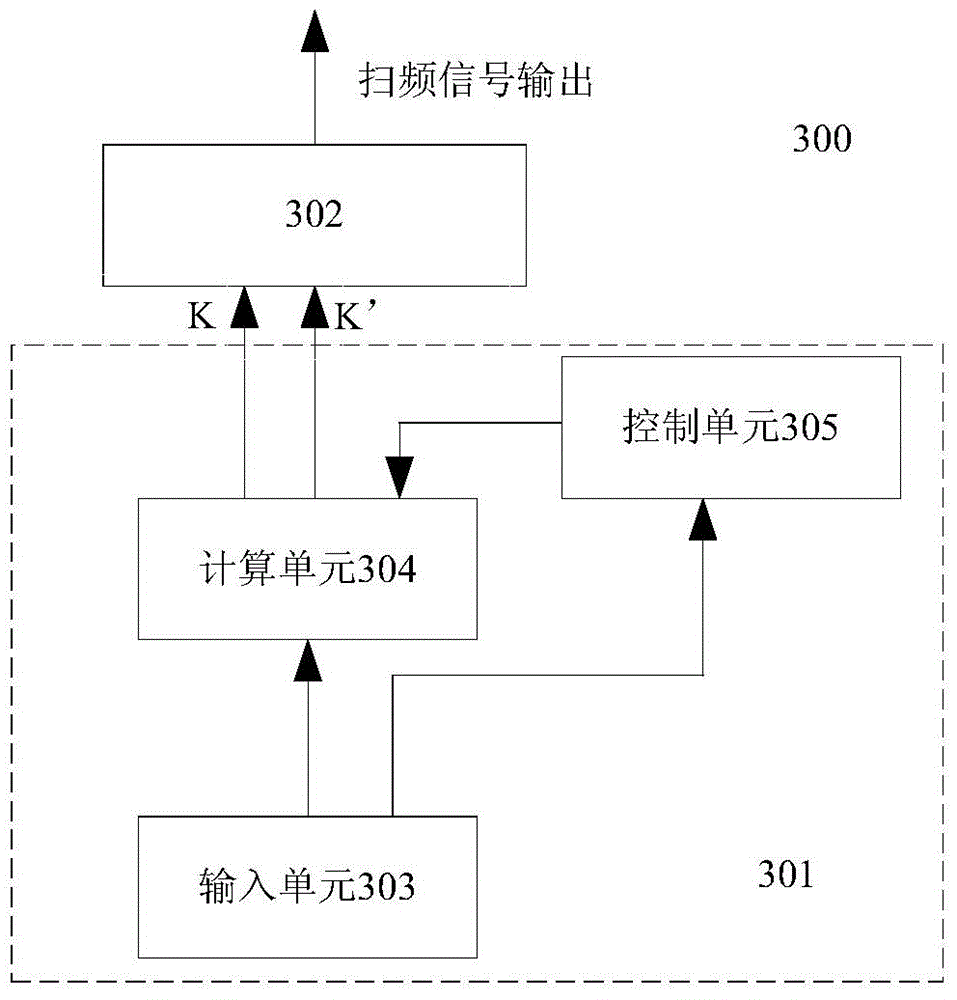
[0055] Attached with reference image 3 , the present invention discloses a signal generator 300 with a frequency sweep function, the signal generator 300 includes a frequency sweep wave table generation unit 301 and a DDS signal source 302; the frequency sweep wave table generation unit 301 includes an input unit 303 , a calculation unit 304 and a control unit 305;

[0056] Wherein, the output end of the input unit 303 is connected to the input end of the calculation unit 304 and the control unit 305 respectively, the output end of the calculation unit 304 is connected to the input end of the DDS signal source 302, and the control unit The output terminal of 305 is connected to the control terminal of the calculation unit 304, a...


PUM


Abstract

The invention provides a signal generator with a frequency sweeping function. The signal generator comprises a frequency sweep wavetable generation unit used for generating a frequency sweep frequency control word; and a DDS (Direct Digital Frequency Synthesis) signal source used for generating a frequency sweep signal according to the frequency sweep frequency control word; the frequency sweep wavetable generation unit comprises an input unit used for generating scanning time, a scanning type, return time, a return type, a starting frequency and an ending frequency according to user input; a calculation unit used for generating a corresponding forward frequency sweep frequency control word according to the scanning time, the scanning type, the starting frequency and the ending frequency, and generating a corresponding return frequency sweep frequency control word according to the return time, the return type, the starting frequency and the ending frequency; and a control unit used for controlling to orderly transmit the forward frequency sweep frequency control word and the return frequency sweep frequency control word to the DDS signal source orderly according to the scanning time and the return time. The signal generator of the invention allows users to respectively set forward scanning and return scanning parameters, so that the flexibility of the frequency sweeping function is increased.

Description

technical field [0001] The invention relates to the technical field of measurement and testing, in particular to a signal generator with a frequency sweep function. Background technique [0002] In the field of measurement and testing technology, the signal generator is a common excitation source, which is mainly used to simulate various real signals, as the input excitation of the circuit or system under test, and provides various performance indicators for the circuit or system under test. simulated environment. Most of the existing signal generators have powerful signal generation capabilities, for example: 1. Can generate basic and commonly used function waveforms, such as sine wave, square wave, triangle wave, sawtooth wave and pulse wave, etc.; 2. Can generate digital and analog modulation 3. It can generate frequency sweep signal with continuous frequency change; 4. It can generate pulse train output of various waveform functions; 5. It can generate arbitrary wavefor...

Claims


Application Information

Patent Timeline
Patent Type & Authority Applications(China)
IPC IPC(8): H03B23/00
Inventor 李秀明叶群松王悦王铁军李维森
Owner SUZHOU RIGOL PRECISION ELECTRIC TECH
Why Eureka
Try Eureka