Mobile station, base station, wireless communication system and communication method
A technology for mobile stations and base stations, applied in the field of mobile stations, can solve the problems of difficult communication distance and large attenuation of radio waves, and achieve the effect of ensuring communication distance and suppressing the reduction of transmission speed.
- Summary
- Abstract
- Description
- Claims
- Application Information
AI Technical Summary
Problems solved by technology
Method used
Image
Examples
Embodiment approach 1
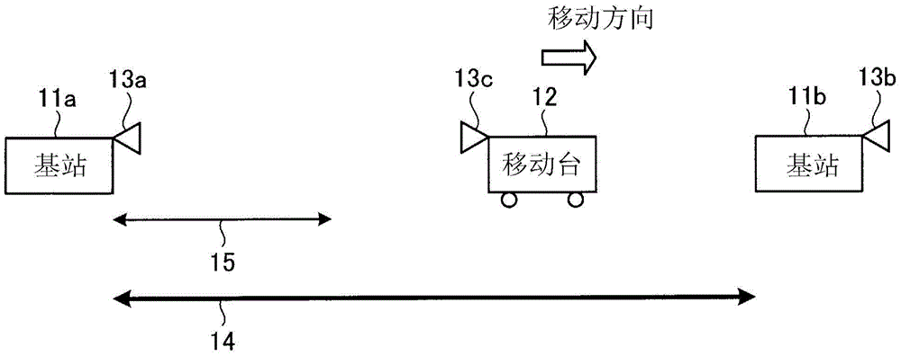
[0021] figure 1 It is a diagram showing a configuration example of Embodiment 1 of the wireless communication system of the present invention. like figure 1 As shown, the wireless communication system of this embodiment includes a base station 11a having a directional antenna 13a, a base station 11b having a directional antenna 13b, and a mobile station 12 having a directional antenna 13c. The number of base stations and mobile stations is not limited to figure 1 example of. The mobile station 12 is mounted on a vehicle such as an automobile or a train, for example, but the unit in which the mobile station 12 moves is not limited to the vehicle.
[0022] figure 1 The clear-sky communication area 14 in the figure indicates an area where communication with the base station 11a is possible when communication parameters are set to realize the maximum transmission rate specified by the wireless communication system of the present embodiment on sunny days. To simplify the descr...
Embodiment approach 2
[0051] Figure 4 It is a diagram showing a configuration example of Embodiment 2 of the mobile station 42 of the present invention. Regarding the configuration of the wireless communication system according to this embodiment, except that the mobile station 12 is replaced by the mobile station 42, and the base stations 11a and 11b are replaced by the base stations 41a and 41b, respectively, the same figure 1 The same wireless communication system. The configuration of the base stations 41a and 41b is the same as that of the mobile station 42 . Hereinafter, parts different from Embodiment 1 will be described.
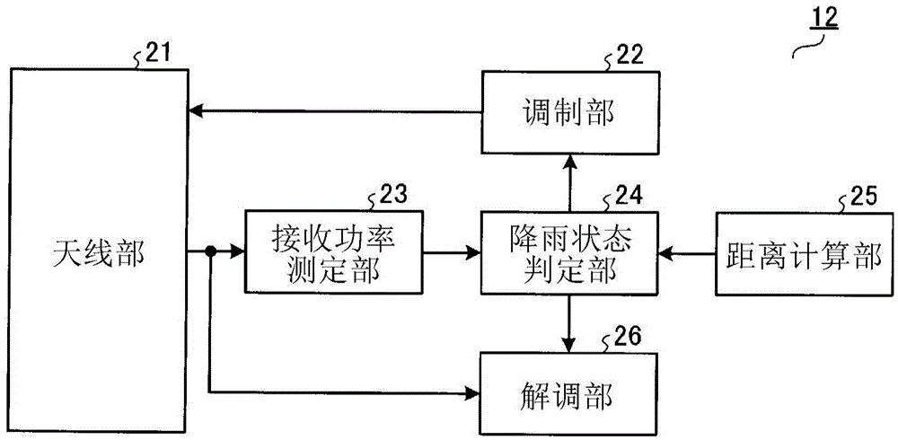
[0052] like Figure 4 As shown, mobile station 42 according to the present embodiment replaces rain state determination unit 24 with rain state determination unit 31 and demodulation unit 26 with demodulation unit 32 in mobile station 12 according to the first embodiment. Components having the same functions as in Embodiment 1 are assigned the same symbols as in Embo...
Embodiment approach 3
[0063] Figure 5 It is a diagram showing a configuration example of Embodiment 3 of the wireless communication system of the present invention. like Figure 5 As shown, the radio communication system of this embodiment is the same as the radio communication system of Embodiment 1 except that the directional antenna 13c of the mobile station 12 is directed in the same direction as the moving direction. The configurations of the mobile station 12 and the base stations 11a and 11b are the same as those of the first embodiment. Hereinafter, parts different from Embodiment 1 will be described. In addition, here, the configuration of the mobile station 12 according to Embodiment 1 will be described as an example. However, in the case where the directing direction of the directional antenna 13c of the mobile station 42 according to Embodiment 2 is set in the same direction as the moving direction, The operation of this embodiment is similarly applied.
[0064] In Embodiments 1 an...
PUM
 Abstract
Description
Claims
Application Information
 - R&D
- Intellectual Property
- Life Sciences
- Materials
- Tech Scout
- Unparalleled Data Quality
- Higher Quality Content
- 60% Fewer Hallucinations
Browse by: Latest US Patents, China's latest patents, Technical Efficacy Thesaurus, Application Domain, Technology Topic, Popular Technical Reports.
© 2025 PatSnap. All rights reserved.Legal|Privacy policy|Modern Slavery Act Transparency Statement|Sitemap|About US| Contact US: help@patsnap.com


