mobile station and base station

一种移动台、基站的技术,应用在移动台领域,能够解决电波衰减量大、通信距离困难等问题,达到确保通信距离、抑制传输速度的降低的效果

Active Publication Date: 2019-03-19
MITSUBISHI ELECTRIC CORP
View PDF6 Cites 0 Cited by
  • Summary
  • Abstract
  • Description
  • Claims
  • Application Information

AI Technical Summary

Problems solved by technology

In particular, high-frequency radio waves such as microwaves and millimeter waves are greatly attenuated by rain.
Therefore, in outdoor wireless communication using radio waves in the high frequency band, it is difficult to secure a communication distance during rain.

Method used


Image

  • mobile station and base station
  • mobile station and base station
  • mobile station and base station

Examples


Embodiment approach 1

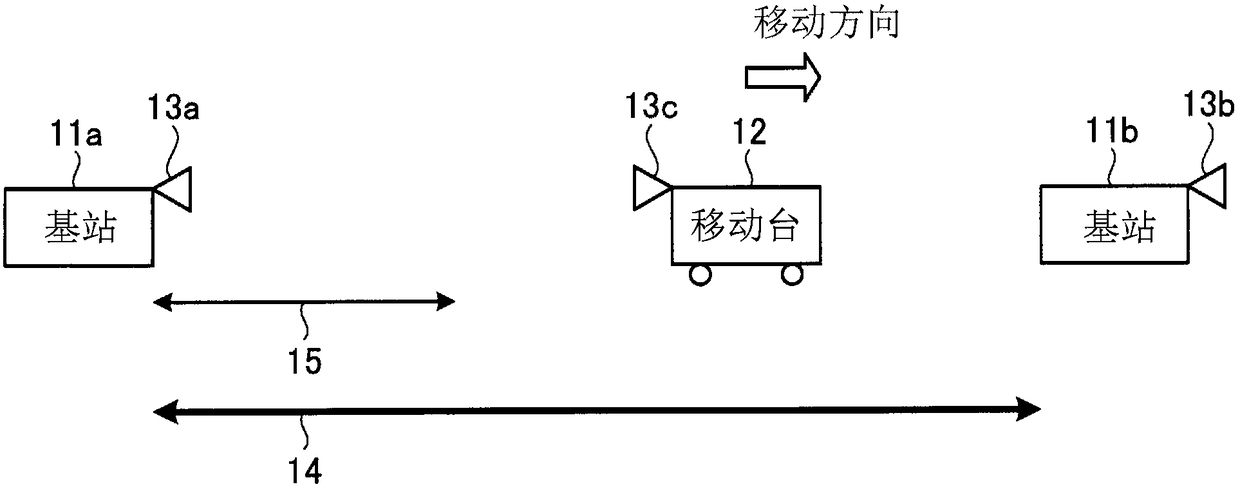
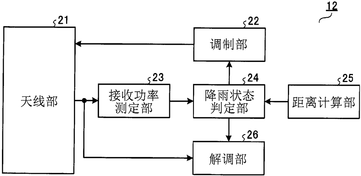
[0021] figure 1 It is a diagram showing a configuration example of Embodiment 1 of the wireless communication system of the present invention. Such as figure 1 As shown, the wireless communication system of this embodiment includes a base station 11a having a directional antenna 13a, a base station 11b having a directional antenna 13b, and a mobile station 12 having a directional antenna 13c. The number of base stations and mobile stations is not limited to figure 1 example of. The mobile station 12 is mounted on a vehicle such as an automobile or a train, for example, but the unit in which the mobile station 12 moves is not limited to the vehicle.

[0022] figure 1 The clear-sky communication area 14 in the figure indicates an area where communication with the base station 11a is possible when communication parameters are set to realize the maximum transmission rate specified by the wireless communication system of the present embodiment on sunny days. To simplify the de...

Embodiment approach 2

[0051] Figure 4 It is a diagram showing a configuration example of Embodiment 2 of the mobile station 42 of the present invention. Regarding the configuration of the wireless communication system according to this embodiment, except that the mobile station 12 is replaced by the mobile station 42, and the base stations 11a and 11b are replaced by the base stations 41a and 41b, respectively, the same figure 1 The same wireless communication system. The configuration of the base stations 41a and 41b is the same as that of the mobile station 42 . Hereinafter, parts different from Embodiment 1 will be described.

[0052] Such as Figure 4 As shown, mobile station 42 according to the present embodiment replaces rain state determination unit 24 with rain state determination unit 31 and demodulation unit 26 with demodulation unit 32 in mobile station 12 according to the first embodiment. Components having the same functions as in Embodiment 1 are assigned the same symbols as in E...

Embodiment approach 3

[0063] Figure 5 It is a diagram showing a configuration example of Embodiment 3 of the wireless communication system of the present invention. Such as Figure 5 As shown, the radio communication system of this embodiment is the same as the radio communication system of Embodiment 1 except that the directional antenna 13c of the mobile station 12 is directed in the same direction as the moving direction. The configurations of the mobile station 12 and the base stations 11a and 11b are the same as those of the first embodiment. Hereinafter, parts different from Embodiment 1 will be described. In addition, here, the configuration of the mobile station 12 according to Embodiment 1 will be described as an example. However, in the case where the directing direction of the directional antenna 13c of the mobile station 42 according to Embodiment 2 is set in the same direction as the moving direction, The operation of this embodiment is similarly applied.

[0064] In Embodiments 1...


PUM


Abstract

A mobile station that communicates with a base station, the mobile station having: a distance calculation unit (25) that calculates the distance between the mobile station and the base station; a received power measurement unit (23) that measures the distance received from the base station The received power of the received signal; the rainfall state judging section (24), which judges the quality of the transmission path based on the theoretical value of the received power corresponding to the distance and the received power measured by the received power measuring section (23), and determines the quality of the transmission path according to the determined transmission path quality A communication parameter is selected; and a modulation unit (22) generates a transmission signal to the base station using the communication parameter.

Description

technical field [0001] The present invention relates to a mobile station, a base station, a wireless communication system and a communication method. Background technique [0002] In a wireless communication system, characteristics of a transmission path change. The movement of the mobile station and the influence of rain can be considered as factors for the change in the characteristics of the transmission path. In particular, radio waves in high-frequency bands such as microwaves and millimeter waves are greatly attenuated by rain. Therefore, in outdoor wireless communication using radio waves in a high frequency band, it is difficult to secure a communication distance during rain. [0003] In order to cope with this problem, Patent Document 1 discloses a wireless communication system that changes a modulation scheme by using received power. Specifically, the measured received power is compared with the received power (required received power) required by the modulation...

Claims


Application Information

Patent Timeline
Patent Type & Authority Patents(China)
IPC IPC(8): H04W28/02H04W28/18H04L12/811
CPCH04W28/18H04W28/0226H04W28/0231H04L47/38H04W24/08H04W40/12H04W40/20
Inventor 塚本薰
Owner MITSUBISHI ELECTRIC CORP
Why Eureka
Try Eureka