Door-knob lock transmission mechanism

A technology of transmission mechanism and doorknob, which is applied in the direction of building structure, building fastening devices, construction, etc., and can solve problems such as inability to actuate, transmission dead point, drive piece cannot be reset, etc.

Inactive Publication Date: 2016-06-22
TAIWAN FU HSING INDAL
View PDF6 Cites 1 Cited by
  • Summary
  • Abstract
  • Description
  • Claims
  • Application Information

AI Technical Summary

Problems solved by technology

[0004] The purpose of the present invention is to provide a transmission mechanism for a doorknob lock. The technical problem to be solved is to avoid the dead p...

Method used


Image

  • Door-knob lock transmission mechanism
  • Door-knob lock transmission mechanism
  • Door-knob lock transmission mechanism

Examples


Embodiment Construction

[0047] In order to further explain the technical means and effects of the present invention to achieve the intended purpose of the invention, the specific implementation, structure, Features and their functions are described in detail below.

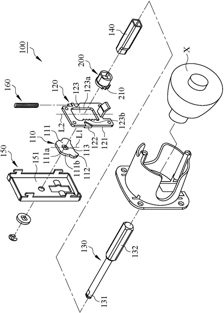
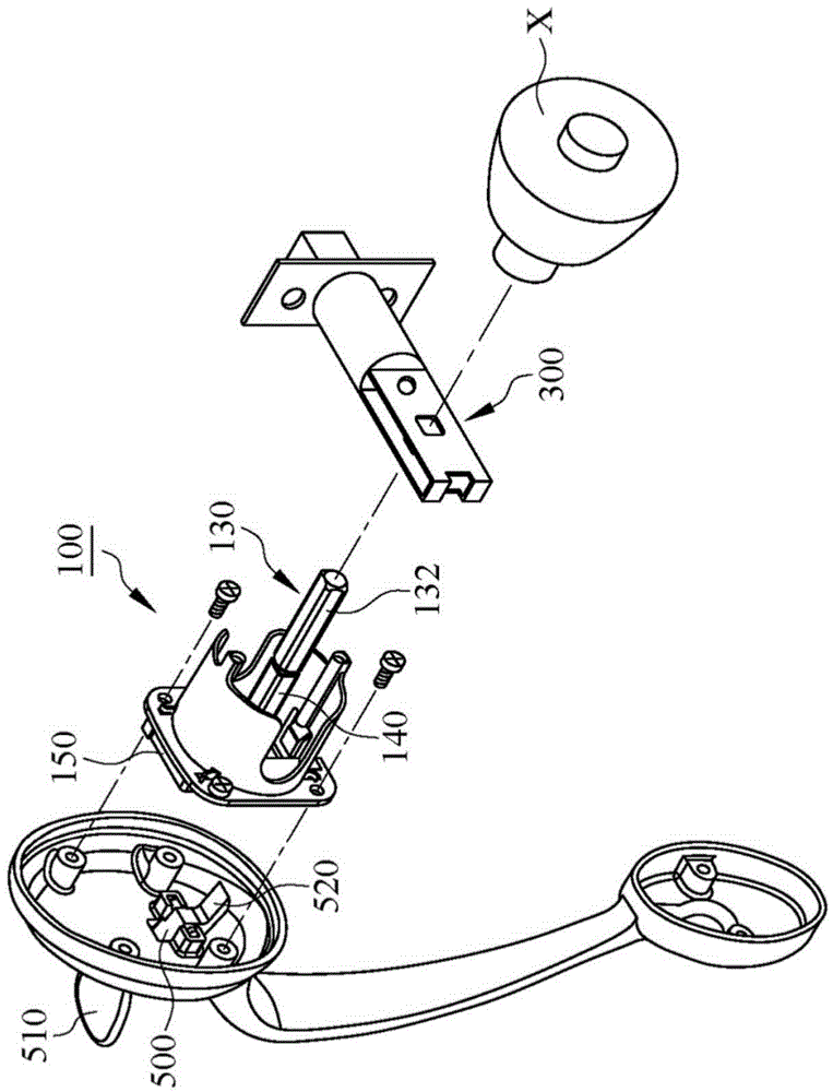
[0048] see figure 1 and figure 2 , is an embodiment of the present invention, a transmission mechanism 100 of a door handle lock, including a driving piece 110 and a transmission plate 120, the driving piece 110 is used to drive the transmission plate 120 to move horizontally or vertically, in this embodiment Taking the vertical movement of the transmission plate 120 as an illustration, when the transmission plate 120 moves vertically, it will drive the rotating member 200 to rotate, and the rotation of the rotating member 200 will synchronously drive the locking bolt 300 to perform the action of extending or retracting the locking bolt. When the door is closed When the lock bolt is extended, when the lock bolt is retracted, the door...


PUM


Abstract

The present invention relates to a door-knob lock transmission mechanism for driving telescopic movement of a latch, the door-knob lock transmission mechanism comprises a drive chip and a transmission plate, the drive chip is provided with a body portion and a top contact portion, the top contact portion is provided with a transmission surface and a stopper surface, the transmission surface is cambered, the stopper surface is flat, the drive chip rotates around a rotation center to allow the top contact portion to swing between a first position and a second position, the transmission plate is provided with a bump, the bump is provided with a contact surface, when the top contact portion of the drive chip is located at the first position, the transmission surface contacts against the contact surface, the transmission surface pushes the bump of the transmission plate to avoid movement incapability caused by generation of transmission dead spots, and when top contact portion of the drive chip swings to the second position, the stopper face contacts against the contact surface, and the stopper face contacts against the contact surface of the bump to prevent resetting incapability of the drive chip caused by over-rotation of the drive chip.

Description

technical field [0001] The invention relates to a transmission mechanism of a door handle lock, in particular to a transmission mechanism of a door handle lock in which a driving plate drives a driving plate to move. Background technique [0002] See US Patent No. 5,088,778 and Figure 11 to Figure 13 , a conventional transmission mechanism 400 for a doorknob lock, which has a driving piece 410, a transmission plate 420 and a cover 430, and the driving piece 410 uses its endpoint 411 to push the cylinder 421 of the transmission plate 420 to move upwards, please refer to Figure 12 , when the transmission plate 420 reaches the transmission dead point in the process of moving (that is, the transmission plate 420 contacts the top of the cover 430), since the end point 411 of the driving piece 410 is in contact with the cylinder 421 of the transmission plate 420 Contact each other with curved surfaces, if a greater force is applied to rotate the driving piece 410 at this time, ...

Claims


Application Information

Patent Timeline
IPC IPC(8): E05C1/14
Inventor 黄昭铭
Owner TAIWAN FU HSING INDAL
Why Eureka
Try Eureka