

Fluid transition path acquisition device, method for acquiring fluid transition path, and program
A technology for migrating paths and obtaining devices, which is applied in the direction of configuring CAD, special data processing applications, instruments, etc., can solve the problems of limited search range, increased calculation time and design cost, and cannot rule out the local optimum of structures, so as to achieve optimization The effect of the method
- Summary
- Abstract
- Description
- Claims
- Application Information
AI Technical Summary
Problems solved by technology
Method used
Image

Examples
Embodiment approach 1
[0113] Outline of the embodiment of the present invention
[0114] Below, refer to Figure 1~Figure 28 The outline of the embodiment of the present invention will be described, and thereafter, the configuration and processing of the embodiment will be described in detail.
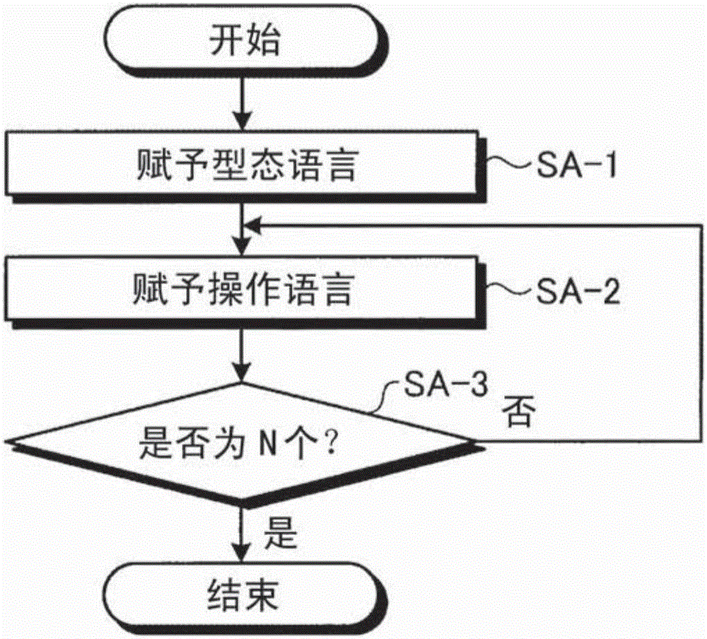
[0115] First, in the present embodiment, pattern transition information is stored, and the pattern transition information relates to a structurally stable flow pattern in the whole or part of the two-dimensional flow structure of phase geometry (hereinafter, also referred to as "streamline pattern") ), through an intermediate flow pattern that is structurally unstable, whether it can migrate to other structurally stable flow patterns. In addition, the method for obtaining this type of transition information for the network will be described later.
[0116] In addition, in the present embodiment, based on the pattern transition information, migration information related to a migration path from a specified structu...
Embodiment
[0349] Here, an embodiment using simulation results will be described. As a premise, for an object placed in a uniform flow, the experimental results or numerical calculation results of the force on the object during a certain period and the flow around the object are stored. Here, the force received by the object is the force received by the object through a uniform flow, specifically, lift or drag. As an example, it may be the lift-to-drag ratio (the ratio of lift to drag).
[0350] here, Figure 32 It is a diagram schematically showing a case where a thin flat plate with a finite thickness is used as an object in a uniform flow in a two-dimensional outer region and placed at an angle with respect to the uniform flow. The symbol U in the figure represents the uniform flow, cl is the length of the longer side of the flat plate, θ is the angle with respect to the uniform flow, and Lx and Ly represent the rectangular area of the calculation subject composed of the lengths in the...
Embodiment approach
[0492] Furthermore, the embodiments of the present invention have been described so far, but the present invention can be implemented in various embodiments within the scope of the technical solution described in the claims in addition to the above-mentioned embodiments.
[0493] In particular, in the above-mentioned embodiment, although an example in which the present invention is applied to a simulated cross section of a three-dimensional fluid (a cross section of a structure, etc.) has been described, it is not limited to this, and can also be applied to a simulation of a two-dimensional fluid. .
[0494] For example, although the case where the fluid migration path acquisition device 100 performs processing in a stand-alone manner is described as an example, the fluid migration path acquisition device 100 may also perform processing according to a request from a client terminal and return the processing result to The client terminal.
[0495] In addition, among the processes des...
PUM
 Abstract
Description
Claims
Application Information