Supercharge Your Innovation With Domain-Expert AI Agents!

Locking mechanism for locking automotive lamps

A technology of locking mechanism and automotive lamps, which can be applied to household appliances, other household appliances, applications, etc. It can solve problems such as difficult to ensure welding position, lower product qualification rate, inaccurate upper and lower positions, etc., and meet processing requirements and matching process requirements Not high, improve product qualification rate, and occupy less space

Active Publication Date: 2017-10-31
CHANGZHOU XINGYU AUTOMOTIVE LIGHTING SYST CO LTD
View PDF6 Cites 0 Cited by
  • Summary
  • Abstract
  • Description
  • Claims
  • Application Information

AI Technical Summary

Problems solved by technology

But when the lamp housing is placed, due to the different heights of the bosses on the outer periphery, and most of them are curved surfaces, it is difficult to ensure the welding position of the lamp housing once placed on the supporting positioning block, resulting in inaccurate upper and lower positions when the lamp shade and the lamp housing are molded and solidified.
Secondly, limited by the space and the shape of the workpiece, the lamp housing cannot be locked. When the lamp housing and lampshade are melted, they also adhere to the upper mold. When the upper mold moves away, the position of the lamp that has not been completely solidified will move, causing The upper and lower positions of the lampshade and the lamp housing are inaccurate when the mold is closed and solidified, which reduces the qualified rate of the product

Method used


Image

  • Locking mechanism for locking automotive lamps
  • Locking mechanism for locking automotive lamps
  • Locking mechanism for locking automotive lamps

Examples


Embodiment Construction

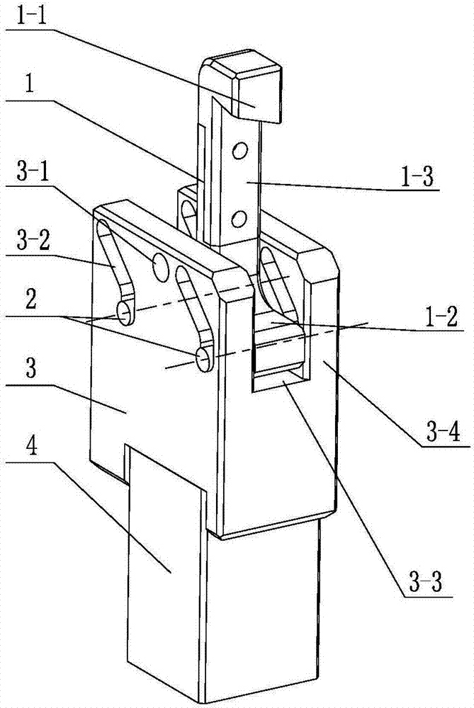
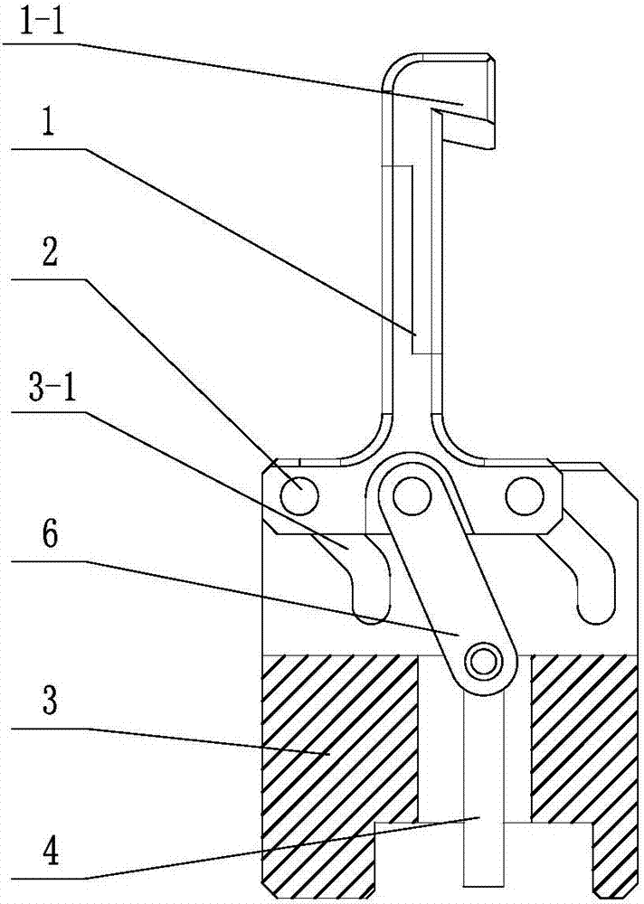
[0020] See figure 1 , 2 The locking mechanism shown for locking the automotive lamps includes a guide support 3, a connecting rod 6, a moving rod 4 for driving the connecting rod 6, and a moving rod 4 extending into the workpiece hole 7-1 and facing the top of the hole. Press down the limit clamping piece 1. See Figure 1~4 As shown, the guide support 3 of the present invention is provided with a guide chute 3-2 for placing the guide pin 2 and moving and guiding the guide pin 2, an upper cavity 3-3 for accommodating the clamping part 1 and for using The lower chamber 3-5 that the moving rod 4 passes through, and the bottom of the guide chute 3-2 is provided with a locking vertical groove, and the upper end of the connecting rod 6 passing through the lower chamber 3-5 is connected to the top of the guide support 3. The clamping part 1 of the cavity 3-3 is connected, and the lower end is connected with the moving rod 4. See figure 1 , 2 As shown, the clamping part 1 of the...


PUM


Abstract

The invention relates to a locking device for locking an automobile lamp. The locking device comprises a guiding support, a connecting rod, a moving rod used for driving the connecting rod to act, and a clamping piece used for stretching into a workpiece hole and pressing and limiting the top face of the hole. The guiding support is provided with guiding inclined grooves, an upper cavity and a lower cavity, the guiding inclined grooves are used for containing guiding pins and guiding the movement of the guiding pins, the upper cavity is used for containing the clamping piece, and the moving rod is made to pass through the lower cavity. A locking vertical groove is formed in the lower portion of each guiding inclined groove, the upper end of the part, penetrating the lower cavity, of the connecting rod is connected with the clamping piece of the upper cavity formed in the guiding support, and the lower end of the part, penetrating the lower cavity, of the connecting rod is connected with the moving rod. A barb-shaped pressing head is arranged on the top of the clamping piece, and the guiding pins connected to the clamping piece are arranged in the guiding inclined grooves formed in the guiding support and can move along the guiding inclined grooves. According to the locking device, a workpiece can be placed in or taken out conveniently, in addition, the contained workpiece can be positioned again and then clamped, and in the upward moving process of an upper die, it can be ensured that the solidification position after die assembly can keep unchanged, and the product pass percent can be increased.

Description

technical field [0001] The invention relates to a locking mechanism for locking an automobile lamp, which belongs to the technical field of automobile lamp manufacturing. Background technique [0002] Motor vehicle lights are mainly composed of light source and reflector or light source, reflector and light distribution mirror. The light source, reflector and light distribution mirror are all installed between the lamp housing and the lampshade. The service life and the brightness of the light beam during use, so the lamp housing and lampshade need to be fixedly connected and kept sealed. [0003] The lamp housing and lampshade of the lamp are made of high polymer plastics, so the lamp housing and lampshade are usually fixedly connected by pressing the welding rod after hot melting. At present, a welding method adopts hot plate welding, and the welding ribs on the cover body and the lampshade are melted by a hot mold, and then pressurized to press and solidify the lamp hous...

Claims


Application Information

Patent Timeline
Patent Type & Authority Patents(China)
IPC IPC(8): B29C65/78B29L31/30
CPCB29C65/7844B29C66/81419B29L2031/30
Inventor 王亚飞刘秋鹏
Owner CHANGZHOU XINGYU AUTOMOTIVE LIGHTING SYST CO LTD
Features
  • R&D
  • Intellectual Property
  • Life Sciences
  • Materials
  • Tech Scout
  • Unparalleled Data Quality
  • Higher Quality Content
  • 60% Fewer Hallucinations
Learn More