Portable wire cable assembly
A cable assembly and cable technology, which is applied in the field of cable bundling, can solve the problems of troublesome sorting and easy winding into a mess, and achieves the effect of avoiding loss and being easy to carry.
- Summary
- Abstract
- Description
- Claims
- Application Information
AI Technical Summary
Problems solved by technology
Method used
Image
Examples
Embodiment 1)
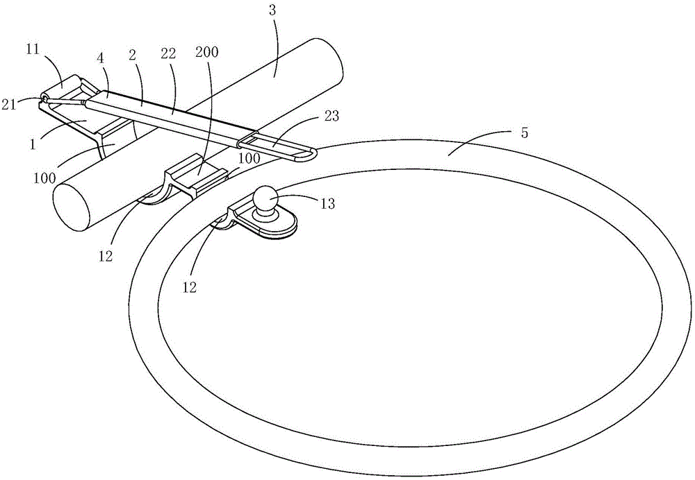
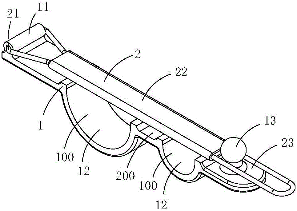
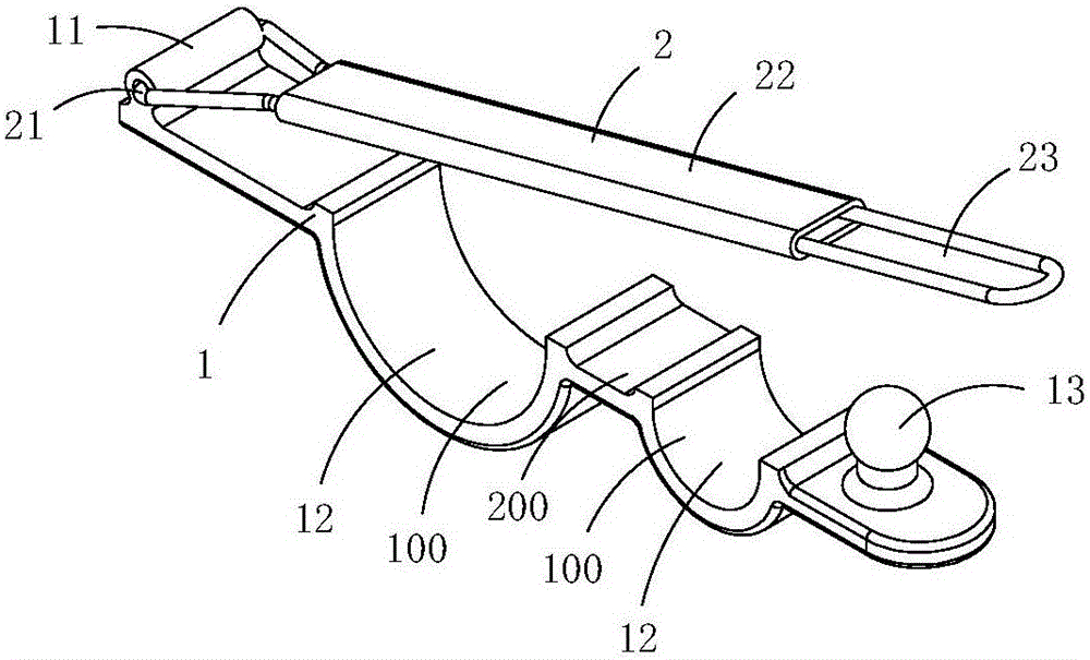
[0015] Figure 1 to Figure 5 A first embodiment of the invention is shown in which, figure 1 It is a schematic diagram of a three-dimensional structure of the first structure of the present invention; figure 2 yes figure 1 A schematic diagram of a three-dimensional structure of the cable assembly shown when the clamp is in a closed state; image 3 yes figure 2 A schematic diagram of a three-dimensional structure of the tensioner shown when it is in an open state; Figure 4 yes figure 2 A front view of the tensioner shown; Figure 5 yes figure 2 A schematic diagram of a three-dimensional structure of the sealing plate in the tensioner shown.
[0016] This embodiment is a portable cable assembly, see Figure 1 to Figure 3 As shown, it includes a cable 3; the cable is provided with a clamp 4 with an elastic ferrule 5, and the clamp includes a clamping plate 1 and a sealing plate 2; one end of the sealing plate is rotatably connected to the clamping plate, and the othe...
Embodiment 2)
[0022] Figure 6 to Figure 8 A second embodiment of the invention is shown, in which Image 6 It is a schematic diagram of a three-dimensional structure of the thread clamp in the second structure of the present invention; Figure 7 yes Image 6 A schematic diagram of a three-dimensional structure of the sealing plate in the clamp shown; Figure 8 yes Figure 7 An exploded view of the cover plate shown.
[0023] This embodiment is basically the same as Embodiment 1, the difference is: see Figure 6 to Figure 8 As shown, the sealing plate 2 includes a cross-shaped rod 6 made of steel wire and a stopper 8 arranged in the middle of the cross-shaped rod, and a gap 62 is provided on one side of the middle part of the cross-shaped rod 6; the stopper 8 There is a sleeve hole 81 at the center of the end plate body on one side, and the end plate body on the other side first extends outward and then rolls up to form a U-shaped chute 82. The opening of the U-shaped chute 82 is locat...
PUM
 Abstract
Description
Claims
Application Information
 - R&D
- Intellectual Property
- Life Sciences
- Materials
- Tech Scout
- Unparalleled Data Quality
- Higher Quality Content
- 60% Fewer Hallucinations
Browse by: Latest US Patents, China's latest patents, Technical Efficacy Thesaurus, Application Domain, Technology Topic, Popular Technical Reports.
© 2025 PatSnap. All rights reserved.Legal|Privacy policy|Modern Slavery Act Transparency Statement|Sitemap|About US| Contact US: help@patsnap.com


