Fluid spraying device for metal surface treatment

A technology for metal surface treatment and spraying device, applied in the direction of spraying device, etc., can solve the problems of high cost and complex structure, etc.

Inactive Publication Date: 2016-07-13
陈亚芳
View PDF5 Cites 1 Cited by
  • Summary
  • Abstract
  • Description
  • Claims
  • Application Information

AI Technical Summary

Problems solved by technology

However, it is difficult for some devices in the prior art to realize such swinging in the widt

Method used


Image

  • Fluid spraying device for metal surface treatment
  • Fluid spraying device for metal surface treatment
  • Fluid spraying device for metal surface treatment

Examples


Embodiment Construction

[0010] Combine below Figure 1-3 The present invention will be described in detail.

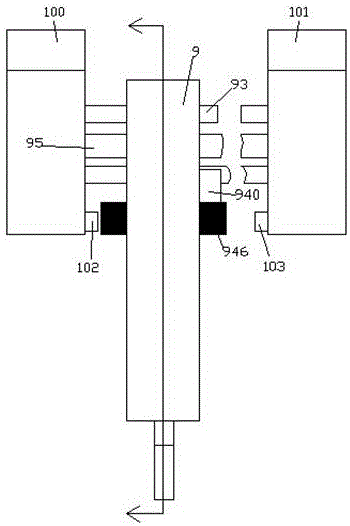
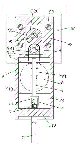
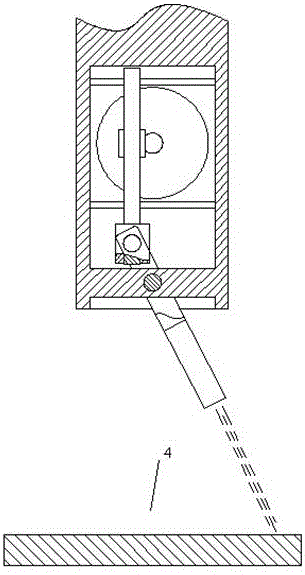
[0011] The fluid spraying device for metal surface treatment according to an embodiment of the present invention is used for spraying fluid to the object 4 to be sprayed, comprising a housing 9 made of an upper supporting portion 92 and a lower driving accommodation portion 91, the upper supporting portion 92 The support is realized by slidingly fitting with a plurality of guide rods 93 fixedly connected to the left fixed base frame 100 and the right fixed base frame 101. The inner cavity 920 of the upper support part 92 is sandwiched with an internally threaded gear plate 96 through a thrust bearing. , the inner circumference of the internally threaded gear plate 96 is provided with an internal thread to cooperate with the walking screw 95 that passes through the inner cavity 920 parallel to the guide rod 93 , and the outer circumference of the internally threaded gear plate 96 Gear teeth a...


PUM


Abstract

A fluid spraying device for metal surface treatment is used for spraying fluid to a sprayed object (4) and comprises a shell (9), wherein the shell (9) is composed of an upper supporting part (92) and a lower driving containing part (91). The upper supporting part (92) is in sliding fit with a plurality of guide rods (93) to achieve supporting, wherein the guide rods (93) are fixedly connected with a left fixing base frame (100) and a right fixing base frame (101). An internal thread gear disc (96) is clamped in an inner cavity (920) of the upper supporting part (92) through thrust bearings, and an internal thread is arranged on the inner circumference of the internal thread gear disc (96) to be matched with a walking threaded rod (95), wherein the walking threaded rod (95) is parallel to the guide rods (93) and penetrates through the inner cavity (920).

Description

technical field [0001] The invention relates to the field of fluid spraying, in particular to a fluid spraying device for metal surface treatment. Background technique [0002] In the prior art, it is often necessary to spray fluid on the surface of some products, such as spraying on the surface of a steel plate for descaling, or spraying derusting oil on the surface of various metal products, such as the surface of a steel plate or a steel pipe. [0003] Since the target product has a certain width, and the spraying part of the spraying or spraying pipe needs to have a certain pressure and the spraying area is limited, therefore, it is necessary to swing the spraying part in the width direction to form a wide spray surface. However, it is difficult for some devices in the prior art to realize such swinging in the width direction while moving in the axial direction. And some similar devices are complex in structure and expensive. Contents of the invention [0004] The ob...

Claims


Application Information

Patent Timeline
IPC IPC(8): B05B13/04
CPCB05B13/0431
Inventor 陈亚芳
Owner 陈亚芳
Why Eureka
Try Eureka