Rotor Blade Extension Part

A rotor blade and extension technology, applied in the field of rotor blade extension, to reduce the risk of leading edge erosion, improve aerodynamic characteristics, and eliminate the impact of aerodynamic noise

Inactive Publication Date: 2016-07-13
SIEMENS AG
View PDF4 Cites 7 Cited by
  • Summary
  • Abstract
  • Description
  • Claims
  • Application Information

AI Technical Summary

Problems solved by technology

Furthermore, such repairs are economically feasible for deviations detected prior to installation of the blade, and the extent of this type of repair can be limited by blade design constraints

Method used


Image

  • Rotor Blade Extension Part
  • Rotor Blade Extension Part
  • Rotor Blade Extension Part

Examples


Embodiment Construction

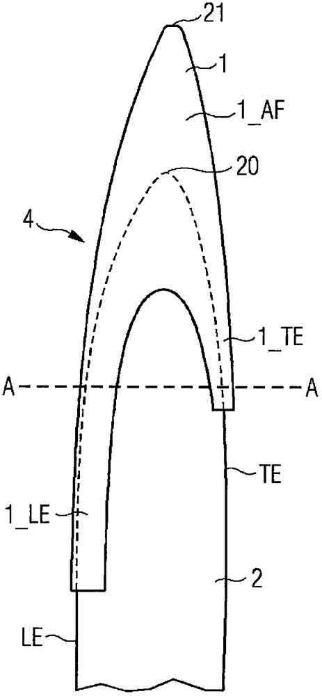
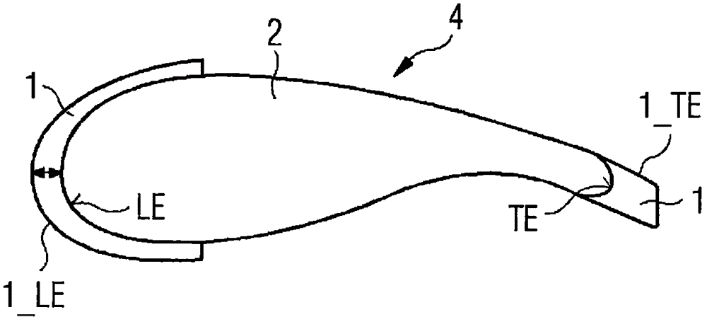
[0045] figure 1 An outboard portion of an extended rotor blade 4 of a wind turbine 3 is shown. The extended rotor blade 4 comprises a first embodiment of the rotor blade extension 1 according to the invention in position on the tip 20 of the rotor blade 2 . The rotor blade 2 comprises a trailing edge TE and a leading edge LE. The rotor blade 2 is tapered, ie pointed, and includes a tip 20 . Reference numeral 20 designates the tip of the "raw" rotor blade 2 , ie the tip of the rotor blade 2 without any rotor blade extension. Once the rotor blade extension 1 is attached to the rotor blade 2, an extended rotor blade 4 is obtained. Reference numeral 21 designates the tip of the extended rotor blade 4 , which is therefore also referred to as “extended tip” 21 .

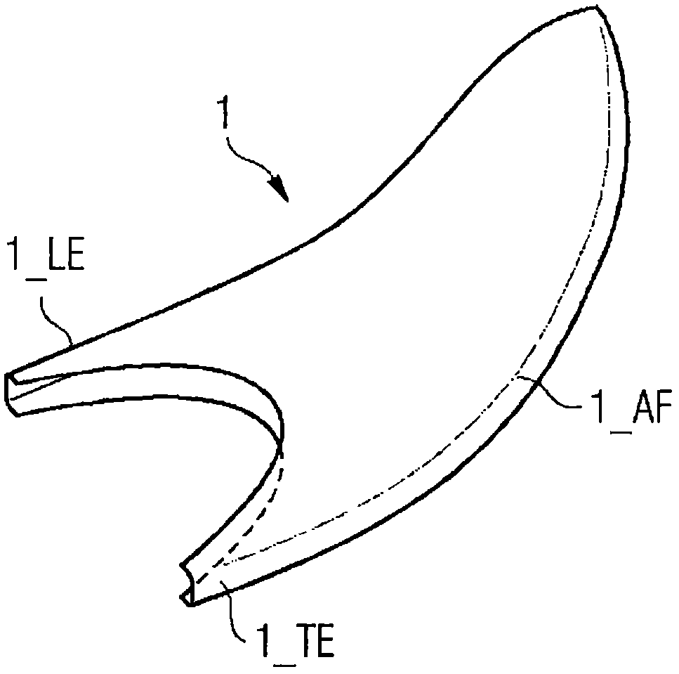
[0046] The rotor blade extension 1 is shown to comprise: an airfoil extension part 1_AF, which effectively extends the length of the rotor blade 2; a leading edge part 1_LE, which is used to cover or extend a part of t...


PUM


Abstract

The invention describes a rotor blade extension part (1) realized for mounting over a tip (20) of a wind turbine (3) rotor blade (2), comprising an airfoil extension portion (1_AF) realized to extend the length (L 2 ) of the rotor blade (2); a leading edge portion (1_LE) realized to cover a profile of the leading edge (LE) of the rotor blade (2); and a trailing edge portion (1_TE) realized to cover a profile of the trailing edge (TE) of the rotor blade (2). The invention further describes a wind turbine (3) comprising a number of rotor blades (2) and a rotor blade extension part (1) according to the invention mounted to each rotor blade (2).

Description

technical field [0001] The present invention describes a rotor blade extension; and a wind turbine. Background technique [0002] Most of the wind energy acting to turn the rotor of a wind turbine generator is captured in the outermost parts of the wind turbine blades, and today's wind turbines are designed with progressively larger rotor diameters, where the rotor diameter is in the rotor The diameter of the circle formed by the tips of the blades as they rotate. [0003] The outermost end of the blade, also called the tip region, is subject to several stringent design criteria, such as leading edge radius, profile contour, torsional orientation, trailing edge thickness, etc. When blades do not meet these design criteria, either through direct manufacturing deviations or through degradation of the leading and / or trailing edges during the lifetime of the wind turbine, the result will be a reduction in the annual energy production (AEP) and noise level of the turbine. Incre...

Claims


Application Information

Patent Timeline
Patent Type & Authority Applications(China)
IPC IPC(8): F03D80/00
CPCF03D1/0675F05B2230/80F05B2250/183F03D80/30F05B2240/307Y02E10/72Y02P70/50F03D1/0633
Inventor A·G·冈萨莱斯S·N·詹森
Owner SIEMENS AG
Why Eureka
Try Eureka