vertebral body fusion

A fusion device and vertebral body technology, applied in the field of vertebral body fusion device, can solve the problems of affecting the treatment effect and being unable to adjust the vertebral body fusion device

Active Publication Date: 2018-08-14
GUANGZHOU ARNOLD MEDICAL DEVICE CO LTD
View PDF8 Cites 0 Cited by
  • Summary
  • Abstract
  • Description
  • Claims
  • Application Information

AI Technical Summary

Problems solved by technology

[0002] In daily life, cases of vertebral body damage due to tumors, fractures, infections, etc. occur from time to time. When treating these patients, the current method used is to implant a fusion device between the damaged vertebral bodies to make the bone tissue produce Crawling substitutes to repair the damaged vertebral body. However, the height of the traditional vertebral body fusion cage is fixed, and the height of the intervertebral body of the human body varies from person to person. It is impossible to adjust the height of the vertebral body fusion cage to suit the different needs of different patients. Intervertebral height, so that the vertebral body fusion device cannot be fully adapted to the intervertebral height of the human body, which affects the treatment effect

Method used


Image

  • vertebral body fusion
  • vertebral body fusion
  • vertebral body fusion

Examples


Embodiment Construction

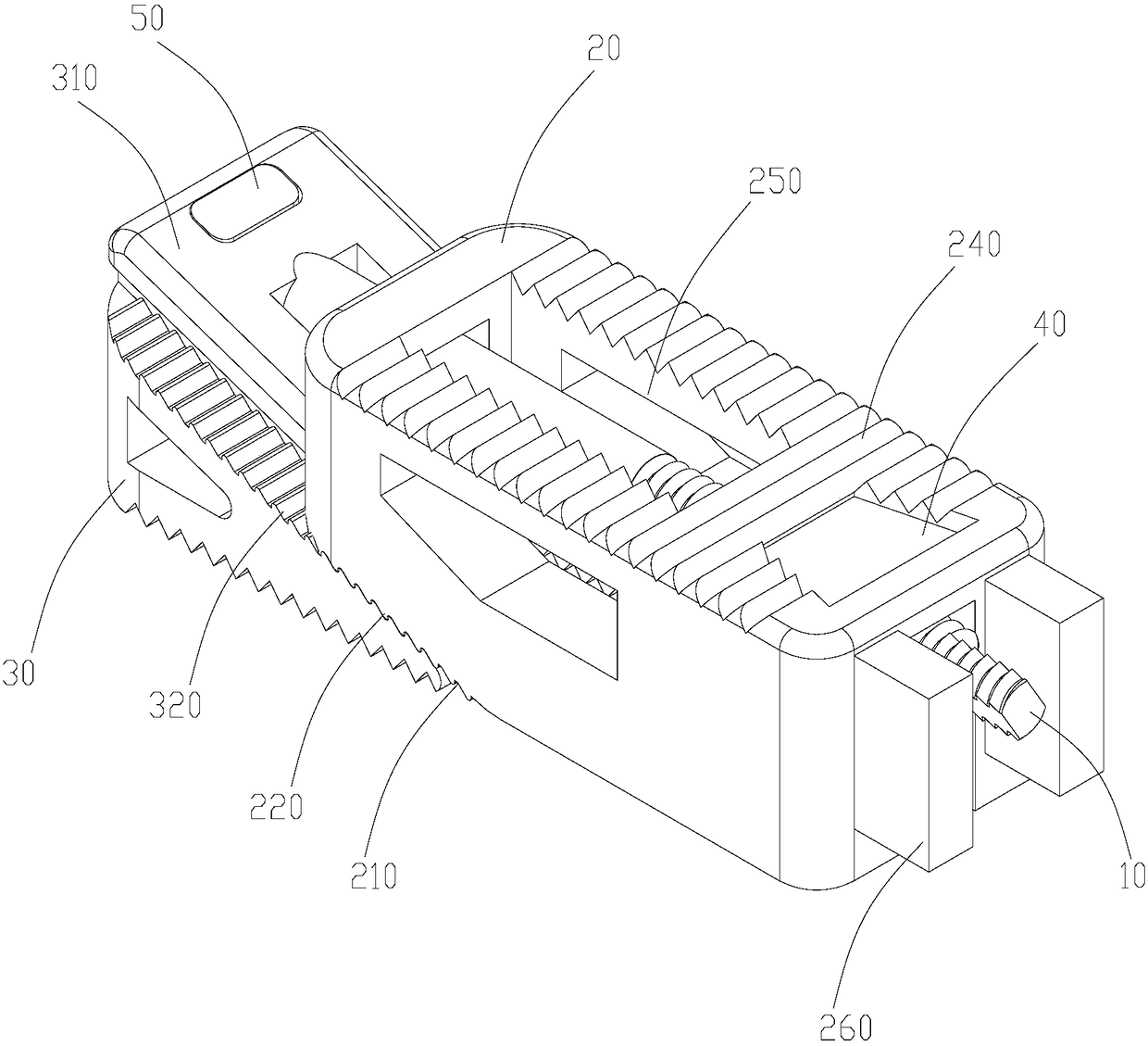
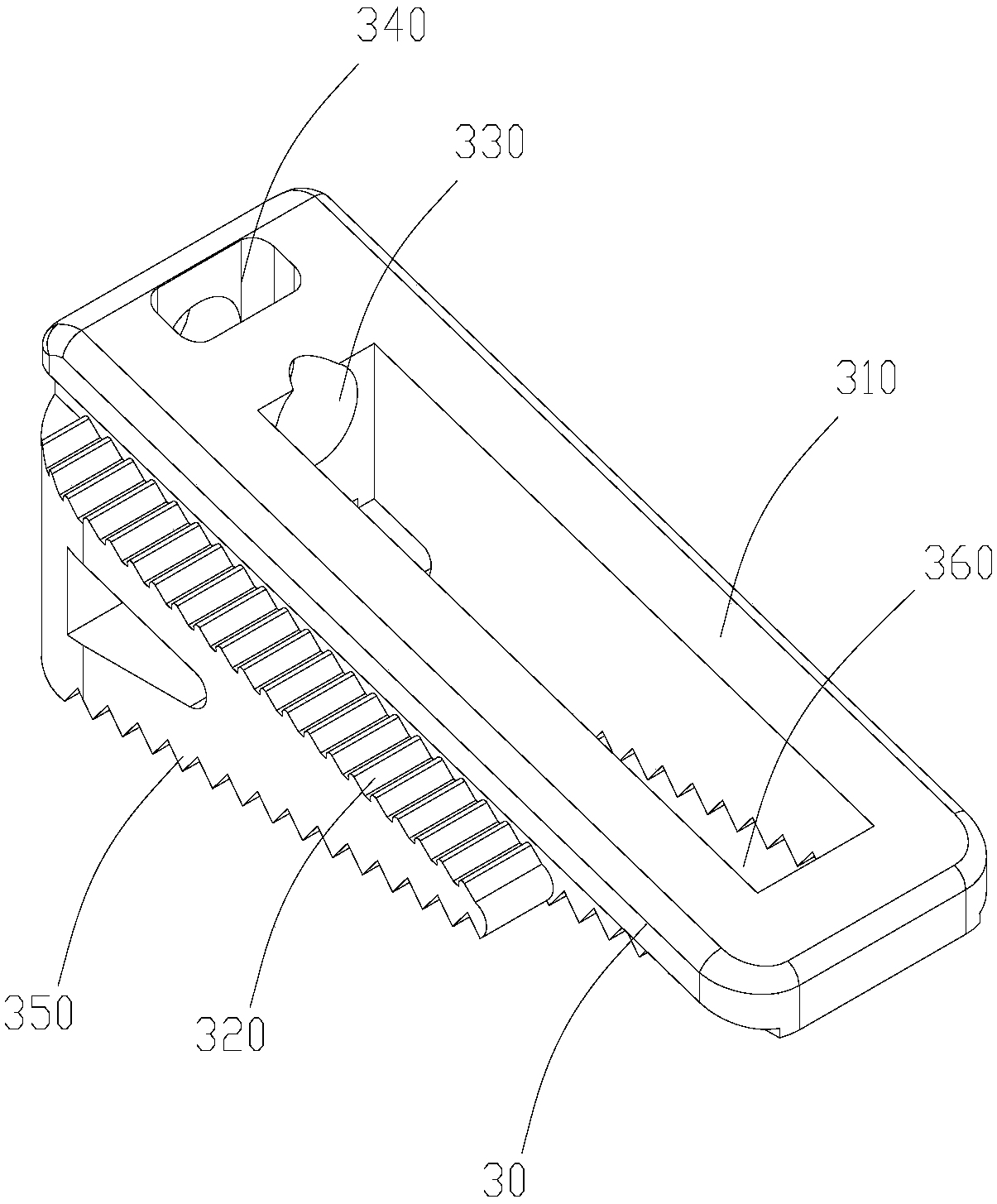
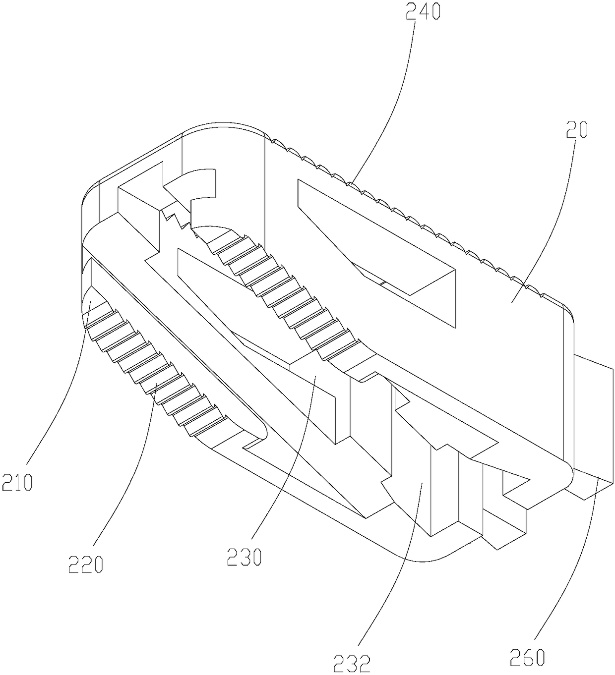
[0030] Such as Figures 1 to 6 As shown, a vertebral body fusion device includes a screw rod 10, an upper plate 20 and a lower plate 30, the upper end surface of the lower plate 30 is a first inclined surface 310, and the lower end surface of the upper plate 20 is provided with a A slope 310 matches the second slope 210, the first slope 310 and the second slope 210 are provided with first anti-slip teeth 220 (320) that can engage with each other, and the lower plate 30 is provided with nuts connected thereto 40 , the nut 40 is sleeved on the screw rod 10 and threadedly connected with the screw rod 10 , the end of the screw rod 10 close to the second slope 210 is limited in the lower plate 30 and is rotatably connected with the lower plate 30 .

[0031] Because the end of the screw rod 10 close to the second slope 210 is limited in the lower plate 30 and is rotatably connected with the lower board 30, by rotating the screw rod 10, the nut 40 threaded with it is driven to move t...


PUM


Abstract

The invention relates to a vertebral fusion cage.The vertebral fusion cage comprises a screw rod, an upper plate and a lower plate.The upper end face of the lower plate is provided with a first slope, the lower end face of the upper plate is provided with a second slope matched with the first slope, and the first slope and the second slope are provided with first anti-slip teeth which can be meshed mutually.A nut connected with the lower plate is arranged in the lower plate and in threaded connection with the screw rod and sleeves the screw rod, and one end, close to the second slope, of the screw rod is limited in the lower plate and rotatably connected with the lower plate.When the screw rod is rotated, the nut in threaded fit with the screw rod is driven to move towards the first slope to drive the upper plate to move upwards along the first slope; when the screw rod is rotated reversely, the nut is driven to move in a direction away from the first slope to drive the upper plate to move downwards along the first slope, so that height adjustment is realized to adapt to different vertebral heights of different patients.By meshing of the first anti-slip teeth for increasing friction, slipping is prevented, and stability is improved.

Description

technical field [0001] The invention relates to the field of medical instruments, in particular to a vertebral body fusion device. Background technique [0002] In daily life, cases of vertebral body damage due to tumors, fractures, infections, etc. occur from time to time. When treating these patients, the current method used is to implant a fusion device between the damaged vertebral bodies to make the bone tissue produce Crawling substitutes to repair the damaged vertebral body. However, the height of the traditional vertebral body fusion cage is fixed, and the height of the intervertebral body of the human body varies from person to person. It is impossible to adjust the height of the vertebral body fusion cage to suit the different needs of different patients. Intervertebral height, so that the intervertebral height of the human body cannot be fully applied to the vertebral fusion device, which affects the therapeutic effect. Contents of the invention [0003] Based ...

Claims


Application Information

Patent Timeline
Patent Type & Authority Patents(China)
IPC IPC(8): A61F2/44
CPCA61F2/4425A61F2/4455
Inventor 赵汝琛
Owner GUANGZHOU ARNOLD MEDICAL DEVICE CO LTD
Why Eureka
Try Eureka