Connector with rotatable locking latch

A connector and electrical connector technology, applied in the direction of connection, parts of connecting devices, coupling devices, etc., can solve the problems of wear, material fatigue of parts, etc.

Active Publication Date: 2019-02-12
TE CONNECTIVITY GERMANY GMBH
View PDF10 Cites 0 Cited by
  • Summary
  • Abstract
  • Description
  • Claims
  • Application Information

AI Technical Summary

Problems solved by technology

[0006] Connectors comprising latches known from the prior art present a problem: by repeated use of the latch, the parts on the plug element and on the latch forming the axis of rotation of the latch are worn and, moreover, even after overcoming the mating force Clamping forces between the plug element and the latch on the one hand and the latch and the mating plug element on the other hand can then lead to fatigue of the material of the part which predetermines the axis of rotation
Disadvantageously, this leads to the fact that only by means of above-average dimensions can these components be made stable enough that they can withstand the Wear and long-term stress due to clamping force

Method used


Image

  • Connector with rotatable locking latch
  • Connector with rotatable locking latch
  • Connector with rotatable locking latch

Examples


Embodiment Construction

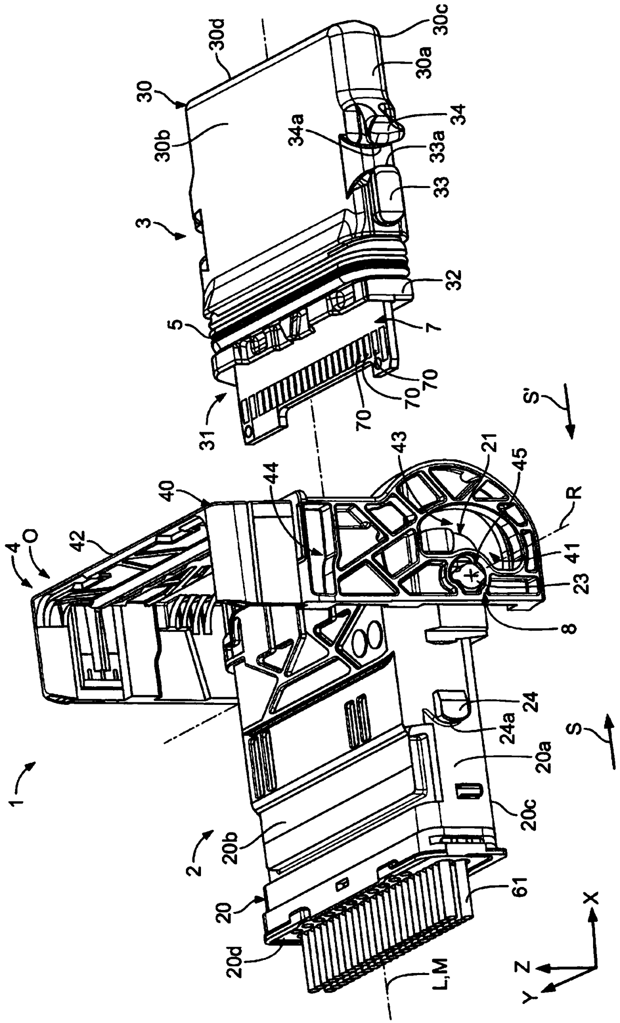
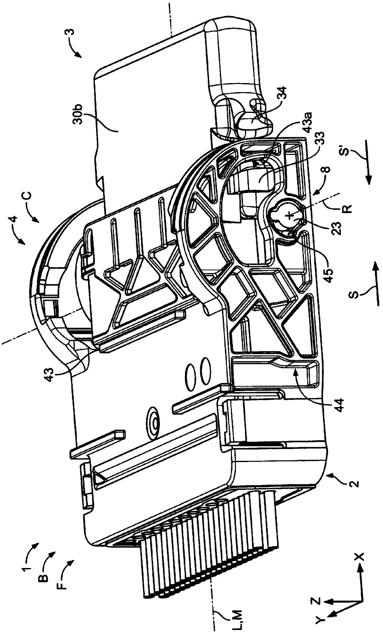
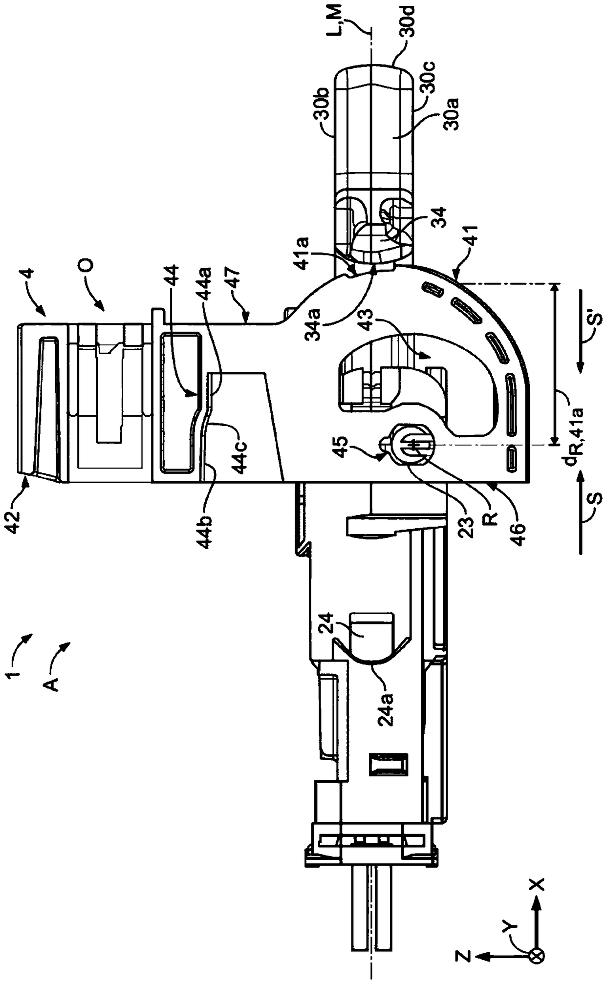
[0036] exist figure 1 , a connector 1 according to the invention is shown in a schematic perspective view. The connector 1 comprises a plug element 2 , a mating plug element 3 and a latch 4 fixed to the plug element 2 . Furthermore, the connector 1 comprises a sealing element 5 , a contact arrangement 6 assigned to the plug element 2 , and a counter contact arrangement 7 assigned to the mating plug element 3 . The plug element 2 and the latch 4 together form a pivot support 8 on which the latch 4 is fixed to the plug element 2 for rotation about the axis R of rotation.

[0037] The connector 1 extends along a longitudinal direction X, a transverse direction Y and a height direction Z, the transverse direction Y extends transversely to the longitudinal direction X, the height direction Z extends transversely to the longitudinal direction X and the transverse direction Y, the longitudinal direction X, the transverse direction Y and the height The directions Z together form a C...


PUM


Abstract

The invention relates to a plug element (2) for an electrical connector (1) comprising a latch (4) rotatable about an axis of rotation (R) from an unlocked position (O) to a lock and the latch has a locking member (43) spaced from the axis of rotation (R). Further, the invention relates to a mating plug element (3) for an electrical connector (1). The invention also relates to an electrical connector (1). In order to unload the axis of rotation (R), according to the solution provided by the invention, in the locking position (C), the locking part (43) engages with the counter locking part (33) of the mating plug element (3), the latch (4) Engaged with the opposing support structure (24), the locking member (43) is supported against the opposing locking member (33) in the direction opposite to the direction of insertion (S), the latch (4) in the direction of insertion (S ) against an opposing support structure (24), in the locked position the plug element (2) engages with the mating plug element (3).

Description

technical field [0001] The invention relates to a plug element for an electrical connector comprising a latch rotatable about an axis of rotation from an unlocked position to a locked position and having a locking member spaced from the axis of rotation. [0002] In addition, the invention relates to mating plug elements for electrical connectors. [0003] The invention also relates to electrical connectors. Background technique [0004] Electrical connectors having plug elements of the type specifically described above and mating plug elements are known from the prior art. The plug element and the mating plug element are usually designed such that they can be joined together in the plug-in direction and counter-plug-in direction, so that the contact element accommodated therein and the counter-contact element contact each other in an electrically conductive manner. [0005] To better overcome the mating forces that occur when plug elements and mating plug elements are mat...

Claims


Application Information

Patent Timeline
Patent Type & Authority Patents(China)
IPC IPC(8): H01R13/639H01R12/77H01R13/506H01R13/629
CPCH01R12/77H01R13/506H01R13/62938H01R13/62955H01R13/639
Inventor D.丁克尔G.帕尼茨
Owner TE CONNECTIVITY GERMANY GMBH
Why Eureka
Try Eureka