A fabric storage device

A fabric and stacking technology, applied in the field of fabric storage, can solve the problems of fabric wrinkles, mildew, fading, etc.

Active Publication Date: 2021-03-30
佛山市顺德区瑞捷服装有限公司
View PDF8 Cites 0 Cited by
  • Summary
  • Abstract
  • Description
  • Claims
  • Application Information

AI Technical Summary

Problems solved by technology

[0002] Stacking fabric rolls in one direction is not conducive to ventilation. The higher the accumulation, the longer it is stored for a long time, the middle part will become moldy, spots will appear on the cotton fabric, and the fabric fastness will decrease. Or a kind of fabric made of various hemp plant fibers, which has strong hygroscopicity, and it will cause wrinkles or fade when stacked unreasonably

Method used


Image

  • A fabric storage device
  • A fabric storage device
  • A fabric storage device

Examples


specific Embodiment approach 1

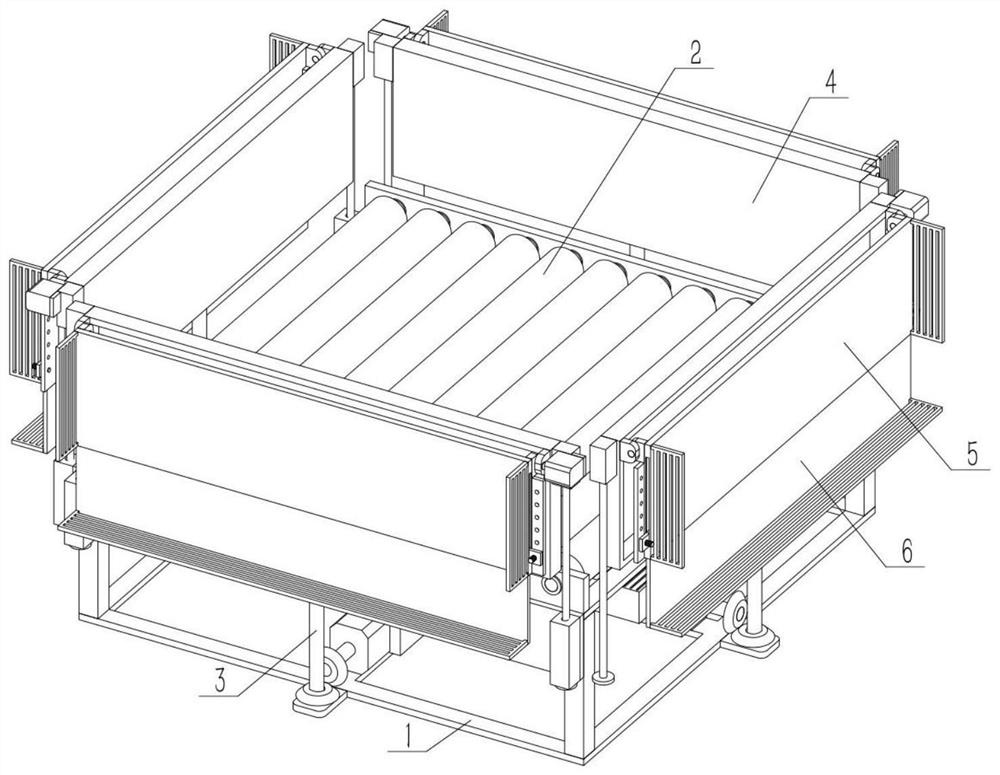
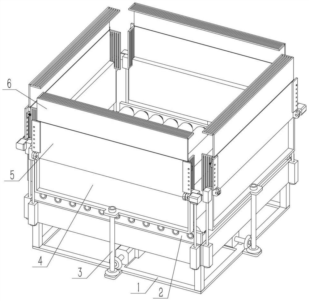
[0031] Such as Figure 1-10 As shown, a fabric stacking device includes a bottom frame 1, a stacking frame 2, a lifting screw 3, a lifting coaming 4, a loading and unloading coaming 5 and an expansion coaming III 6, and the upper end of the bottom frame 1 is fixedly connected to the stacking Frame 2, four lifting screw 3 are provided with, and four lifting screw 3 are respectively rotated and connected around the bottom frame 1, four lifting coamings 4 are provided with, and four lifting coamings 4 are respectively connected with stacking frame 2. Sliding connection around, four lifting coamings 4 are threadedly connected with four lifting screw 3 respectively, there are four loading and unloading coamings 5, four loading and unloading coamings 5 ​​are respectively connected with four lifting coamings 4, expansion coaming III 6 There are four, and the four expansion coamings III 6 are respectively connected with the four loading and unloading coamings 5 ​​. Roller 203 can mak...

specific Embodiment approach 2

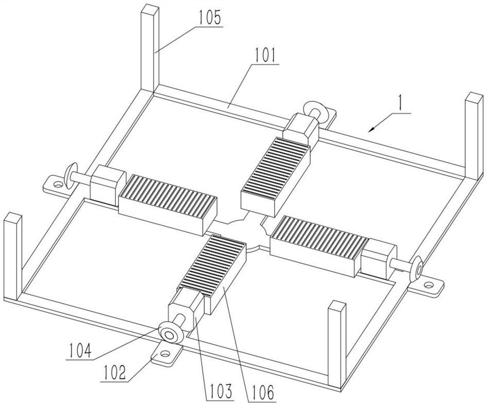
[0033] Such as Figure 1-10 As shown, the bottom frame 1 includes a bottom frame body 101, a bottom connection portion 102, a motor I 103, a helical gear I 104, and a pole 105, and the middle parts around the bottom frame body 101 are respectively fixed with a bottom connection portion 102, and the bottom frame A motor I103 is respectively fixed on the four sides of the body 101, a helical gear I104 is respectively fixed on the output shafts of the four motors I103, and a strut 105 is respectively fixed on the four corners of the bottom frame body 101. One of the motors I103 can be started, the output shaft of the motor I103 drives the helical gear I104, and the helical gear I104 drives the helical gear II302 engaged with it to rotate.

specific Embodiment approach 3

[0035] Such as Figure 1-10 As shown, the bottom frame 1 further includes air blowers 106 , and four air blowers 106 are evenly fixed in the circumferential direction of the bottom frame body 101 . Start the hot air blower 106 to convey hot air upwards from the bottom of the fabric rolls. Combined with the stacking method, there is a gap between the rolls, and the hot air can pass through each layer of fabric rolls, which helps the fabric rolls to dry and prevent moisture in humid weather. , can change the quantity of starting hot air blower 106 according to the situation.


PUM


Abstract

The invention relates to the field of fabric storage, in particular to a fabric stacking device. The fabric stacking device comprises a bottom frame, a stacking frame, lifting screw rods, lifting surrounding plates, loading and unloading surrounding plates and expanding surrounding plates III. Due to rollers, a fabric roll on the bottommost layer cannot move, and fabric rolls at a high position can be better stacked. Due to increasing of the fabric roll stacking height, three-section type lifting surrounding of the fabric rolls can be conducted by lifting the lifting surrounding plate, overturning the loading and unloading surrounding plate and drawing out the expanding surrounding plate III, it can be ensured that a fabric stack is not scattered when accidents happen, equipment moving isfacilitated, and stability of the fabric stack is ensured. Due to the fact that the horizontal arrangement of the loading and unloading surrounding plate is overturned and due to descending of the lifting surrounding plate, the fabric rolls can directly roll on a loading and unloading surrounding plate body, and the fabric rolls can be better unloaded.

Description

technical field [0001] The invention relates to the field of fabric storage, in particular to a fabric stacking device. Background technique [0002] Stacking fabric rolls in one direction is not conducive to ventilation. The higher the accumulation, the longer it is stored for a long time, the middle part will become moldy, spots will appear on the cotton fabric, and the fabric fastness will decrease. Or a kind of fabric made of various hemp plant fibers, which is extremely hygroscopic, and it will cause wrinkles or fade when stacked unreasonably. Contents of the invention [0003] The object of the present invention is to provide a fabric stacking device, which can assist in reasonable stacking and unloading of fabric rolls. [0004] The purpose of the present invention is achieved through the following technical solutions: [0005] A fabric stacking device, comprising a bottom frame, a stacking frame, a lifting screw, a lifting coaming, a loading and unloading coaming...

Claims


Application Information

Patent Timeline
Patent Type & Authority Patents(China)
IPC IPC(8): B65G57/03B65G57/20
CPCB65G57/03B65G57/20B65G2201/0232
Inventor 段建国
Owner 佛山市顺德区瑞捷服装有限公司
Why Eureka
Try Eureka