A riveting mechanism using leverage to increase force

A lever and riveting technology, applied in relays, electrical components, circuits, etc., can solve the problems of labor, reduction, and unfavorable energy consumption, and achieve the effects of small working space, avoiding rebound, and saving space

Active Publication Date: 2018-06-05
BOZHON PRECISION IND TECH CO LTD
View PDF6 Cites 0 Cited by
  • Summary
  • Abstract
  • Description
  • Claims
  • Application Information

AI Technical Summary

Problems solved by technology

[0002] The riveting mechanism, for example, the riveting mechanism for riveting the iron ring of the relay, the power element drives the riveting head directly and horizontally, which is laborious and not conducive to the reduction of energy consumption

Method used


Image

  • A riveting mechanism using leverage to increase force
  • A riveting mechanism using leverage to increase force
  • A riveting mechanism using leverage to increase force

Examples


Embodiment Construction

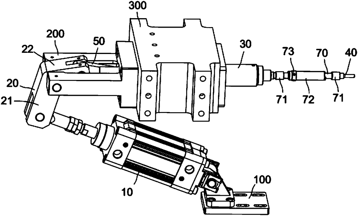
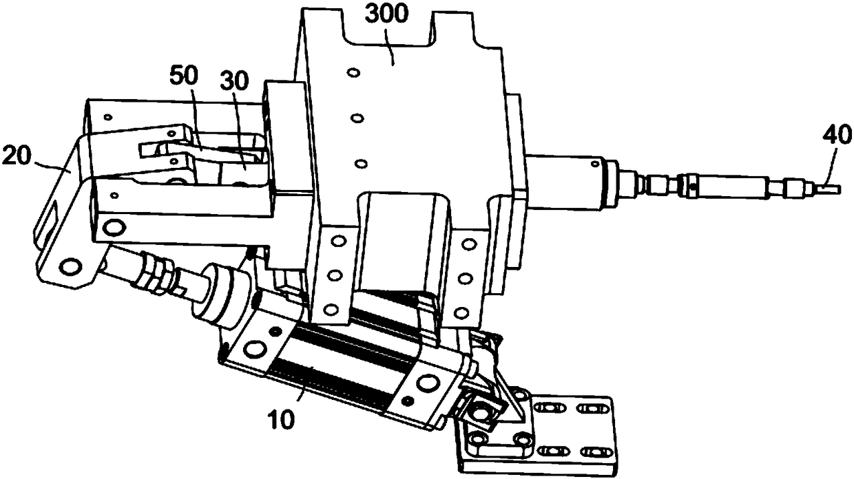
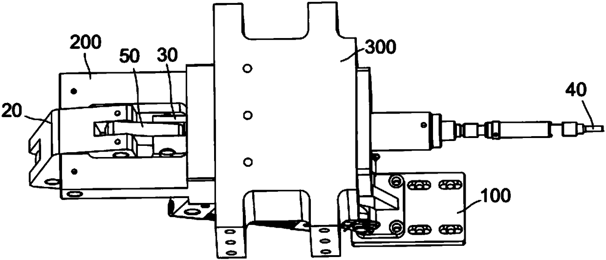
[0023] combine Figure 1 to Figure 3 , a riveting mechanism that uses leverage to increase force, including a push cylinder 10, a lever 20 hinged on a lever seat 200 and one end hinged to the piston rod of the push cylinder, a push rod 30 linked with the lever, and guiding the push rod The push rod guide seat 300 and the riveting head 40 fixedly arranged on the push rod; .

[0024] The cylinder body of the pushing cylinder 10 is hinged on the bottom plate 100 of the pushing cylinder, and the bottom plate of the pushing cylinder is fixedly arranged. The direction the rod is going.

[0025] The lever 20 is V-shaped. The V-shaped lever includes a first straight portion 21 and a second straight portion 22. The hinge of the lever and the lever seat 200 is located at the intersection of the first straight portion and the second straight portion. The piston rod of the cylinder 10 is hinged to the first straight portion, and the connecting rod 50 is hinged to the second straight po...


PUM


Abstract

The invention relates to a riveting and pressing mechanism utilizing a lever for force increasing. The riveting and pressing mechanism comprises a push air cylinder, the lever hinged to a lever base, a push rod linked with the lever, a push rod guide base for guiding the push rod, and a pressing and riveting head fixedly arranged on the push rod, wherein one end of the lever is hinged to a piston rod of the push air cylinder; and the lever is connected with the push rod through a connecting rod, the connecting relation of the connecting rod and the lever is the hinge connection, and the connecting relation of the connecting rod and the push rod is the hinge connection. Due to arrangement of the lever, the mechanism has the force increasing effect; due to arrangement of the connecting rod, the mechanism has the self-locking function, and the rebound phenomenon appearing in the riveting and pressing process is avoided; and the folding type push air cylinder is adopted, and the effect of saving space is achieved.

Description

technical field [0001] The invention relates to a riveting mechanism, in particular to a riveting mechanism utilizing a lever to increase force. Background technique [0002] For the riveting mechanism, for example, the riveting mechanism for riveting the iron ring of the relay, the power element drives the riveting head by direct horizontal pushing, which is laborious and not conducive to the reduction of energy consumption. The utility model with the application number CN201520364342.1 discloses an improved HDMI head iron shell pulling and pressing machine. The second cylinder is connected to one end of the pull rod through a telescopic rod, and the other end of the pull rod is connected to the riveting and pressing rod through a pin shaft. The middle part of the pull rod is hinged on the support seat, and the length of the pull rod between the telescopic rod and the support seat is greater than the length of the pull rod between the riveting rod and the support seat. The...

Claims


Application Information

Patent Timeline
Patent Type & Authority Patents(China)
IPC IPC(8): B21J15/16B21J15/18H01H49/00
CPCB21J15/16B21J15/18H01H49/00
Inventor 吕绍林陈小刚饶元夏春明
Owner BOZHON PRECISION IND TECH CO LTD
Why Eureka
Try Eureka