Supercharge Your Innovation With Domain-Expert AI Agents!

projection device

An orthographic projection and electronic device technology, applied in the field of projection devices, can solve the problems affecting the display function of the projection device, noise, etc., and achieve the effect of avoiding the generation of noise and the use of functions

Inactive Publication Date: 2018-01-30
QISDA OPTRONICS (SUZHOU) CO LTD +1
View PDF5 Cites 0 Cited by
  • Summary
  • Abstract
  • Description
  • Claims
  • Application Information

AI Technical Summary

Problems solved by technology

[0003] However, if the sound generating device is added to the projection device, even if the sound generating device is not in contact with the side wall and the top of the casing, the sound generating device needs the housing to provide a supporting force due to gravity, so the sound generating device will inevitably contact the shell. The bottom of the projection device is in contact with the bottom of the body, and the bottom of the housing of the projection device is in contact with the sound, which will cause the following problems: when the sound generating device is playing sound, the vibration of the sound generating device will drive the vibration of the projection device in contact with it, that is, the projection device will be in contact with the sound generating device. The device generates resonance, causing noise or affecting the display function of the projection device

Method used


Image

  • projection device
  • projection device
  • projection device

Examples


Embodiment Construction

[0026] In order to have a further understanding of the purpose, structure, features, and functions of the present invention, the following detailed descriptions are provided in conjunction with the embodiments.

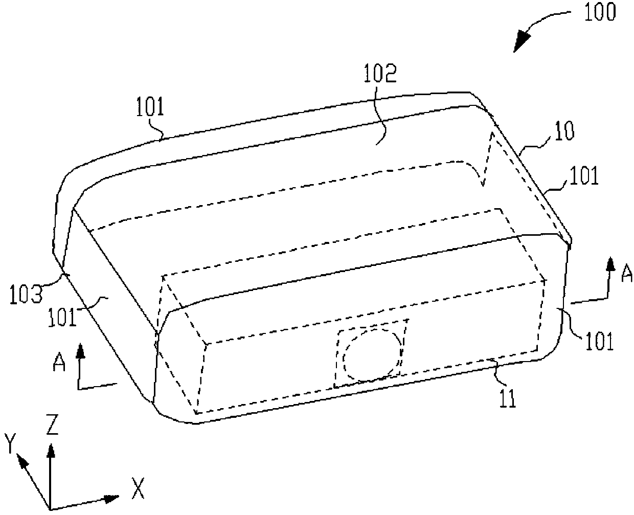
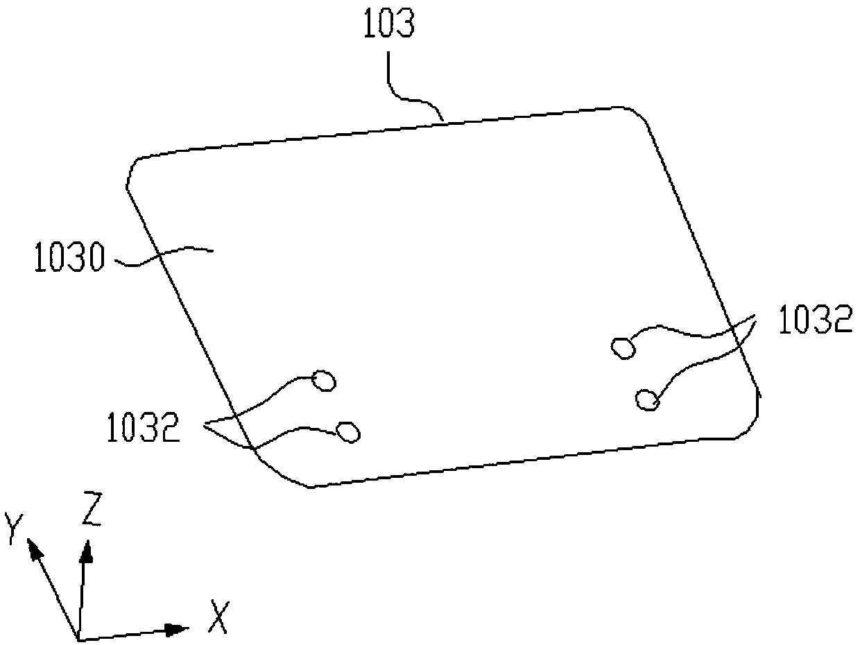
[0027] see Figure 1-Figure 6 as shown, figure 1 is a schematic structural diagram of the electronic device 100 proposed by the embodiment of the present invention, figure 2 for figure 1 The structural schematic diagram of the sound generating device 11 of the electronic device 100 is shown, image 3 for figure 1 The schematic structural diagram of the bottom 103 of the housing 10 of the electronic device 100 is shown, Figure 4 for figure 1 A schematic diagram of a partial structure of the electronic device 100 shown, Figure 5 The edge of the electronic device 100 in the first state proposed by the embodiment of the present invention figure 1 The A-A sectional schematic diagram, Image 6 The edge of the electronic device 100 in the second state proposed by ...


PUM


Abstract

The present invention discloses an electronic device. The electronic device is disposed on a first plane and comprises housing and a sound production device; the sound production device is arranged in the housing and does not contact with a plurality of side walls and top portion of the housing; the bottom of the housing is provided with a first support structure and a first combination part; the second bottom surfaces of the sound production device is provided with a second support structure, and the second support structure extends out of the bottom from the first combination part to match the first plane; and when the electronic device is located at a second state, there is a gap between the first bottom surface and the second bottom surface, therefore, when the sound production device generates vibration caused by sound production, the housing cannot contact with the sound production to generate resonance, the generation of noise is avoided, and the function application of the electronic device cannot be influenced.

Description

technical field [0001] The invention relates to a projection device, in particular to a projection device which has a sound and does not resonate with a shell of the projection device when the sound is played. Background technique [0002] A projection device is a device that can project images or videos onto a screen to achieve a large-screen projection display to provide viewers with excellent presentation and visual effects. In order to increase the added value of the projection device, a sound emitting device is added inside the projection device, so that the projection device can provide a better audio experience while providing a visual experience, that is, provide users with a good audio-visual experience at the same time, and further improve user experience. . [0003] However, if the sound generating device is added to the projection device, even if the sound generating device is not in contact with the side wall and the top of the housing, the housing must provide...

Claims


Application Information

Patent Timeline
Patent Type & Authority Patents(China)
IPC IPC(8): H04N9/31
CPCH04N9/3141
Inventor 卢仁凯
Owner QISDA OPTRONICS (SUZHOU) CO LTD
Features
  • R&D
  • Intellectual Property
  • Life Sciences
  • Materials
  • Tech Scout
  • Unparalleled Data Quality
  • Higher Quality Content
  • 60% Fewer Hallucinations
Learn More