Fluidized bed sludge incinerator and incineration treatment method
A sludge incineration and fluidized bed technology, applied in the direction of combustion method, incinerator, combustion type, etc., can solve problems such as poor sand flow, reduced combustion efficiency, and failure to maintain the specified value of sand temperature
- Summary
- Abstract
- Description
- Claims
- Application Information
AI Technical Summary
Problems solved by technology
Method used
Image

Examples
no. 1 approach
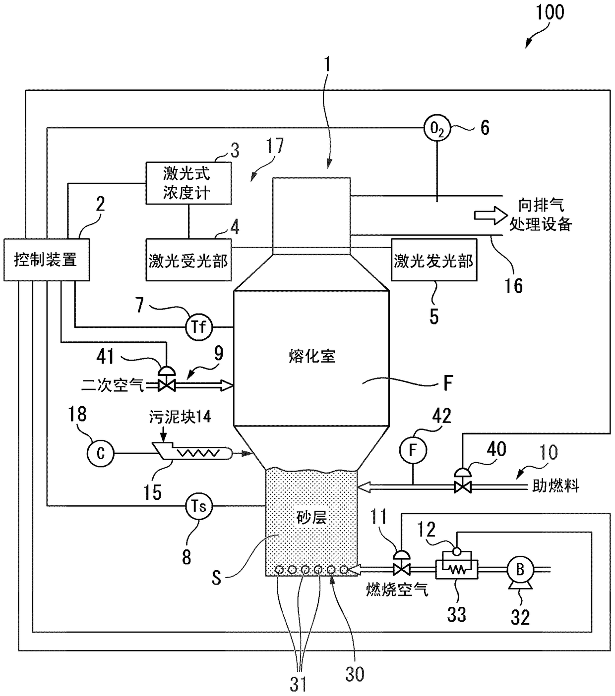
[0080] Hereinafter, a fluidized-bed sludge incinerator according to a first embodiment of the present invention and an incineration treatment method using the fluidized-bed sludge incinerator will be described in detail with reference to the drawings. figure 1 It is a schematic configuration diagram of the fluidized-bed sludge incinerator 100 of this embodiment. The fluidized-bed sludge incinerator 100 is a combustion furnace that uses sand as a heat medium together with sludge to form a fluidized bed of bubbles and burns.
[0081] Such as figure 1 As shown, the fluidized bed sludge incinerator 100 has: an incinerator main body 1 supplied with a sludge lump 14 as sludge; and combustion air is blown to a sand layer S (fluid bed) provided at a lower part of the incinerator main body 1 (primary air) diffuser 30 as a combustion air supply device; and the control device 2 . The part above the sand layer S of the incinerator main body 1 becomes the melting chamber part F.
[0082...
no. 2 approach
[0143]Hereinafter, a fluidized-bed sludge incinerator according to a second embodiment of the present invention will be described with reference to the drawings. It should be noted that, in this embodiment, the description will focus on the differences from the first embodiment described above, and the description of the same parts will be omitted.
[0144] Such as Figure 11 As shown, the air diffuser 30B (combustion air supply device) of the fluidized bed sludge incinerator of this embodiment has: a dispersion plate 43 filled with a sand layer S above; and a wind box provided below the dispersion plate 43 44. The wind box 44 is an introduction part of combustion air, and the sand layer S and the wind box 44 are separated by the dispersion plate 43 .
[0145] A plurality of air supply holes 45 are formed in the diffuser plate 43 . Although not shown in the figure, the air supply hole 45 penetrates the entire surface of the distribution plate 43 . A combustion air nozzle 4...
PUM
 Abstract
Description
Claims
Application Information