Supercharge Your Innovation With Domain-Expert AI Agents!

Fluidized bed type sludge incinerator and incineration treatment method

A sludge incineration and fluidized bed technology, which is applied in the combustion method, incinerator, combustion type, etc., can solve the problems such as the inability of the sand layer temperature to maintain the specified value, the poor flow of the sand layer, and the reduction of combustion efficiency.

Active Publication Date: 2016-08-10
MITSUBISHI HEAVY IND ENVIRONMENTAL & CHEM ENG CO LTD
View PDF10 Cites 1 Cited by
  • Summary
  • Abstract
  • Description
  • Claims
  • Application Information

AI Technical Summary

Problems solved by technology

[0007] However, if the primary air ratio is reduced to less than 0.9, there will be fundamental problems such as a reduction in the amount of combustion in the sand layer, causing the temperature of the sand layer to fail to maintain a specified value, causing poor flow of the sand layer, and reducing combustion efficiency.

Method used


Image

  • Fluidized bed type sludge incinerator and incineration treatment method
  • Fluidized bed type sludge incinerator and incineration treatment method
  • Fluidized bed type sludge incinerator and incineration treatment method

Examples


no. 1 approach

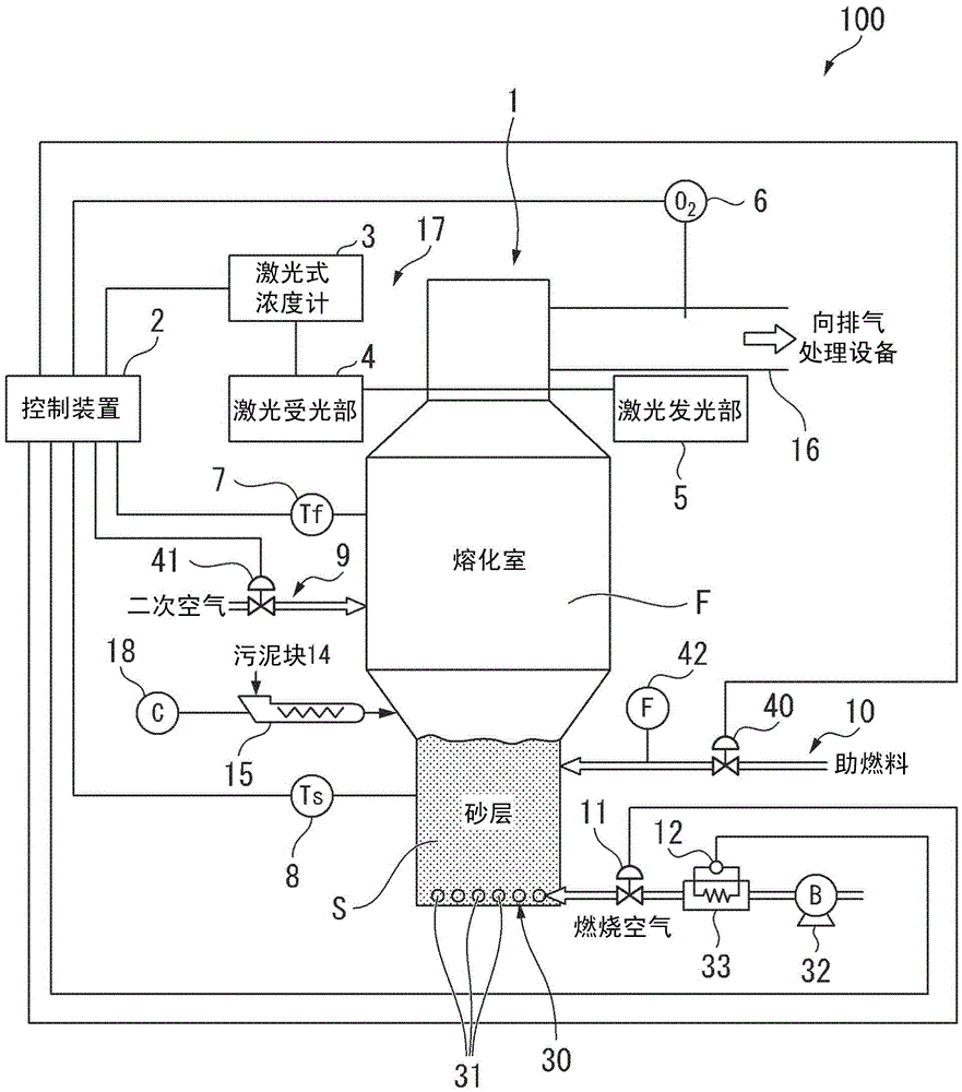
[0080] Hereinafter, a fluidized-bed sludge incinerator according to a first embodiment of the present invention and an incineration treatment method using the fluidized-bed sludge incinerator will be described in detail with reference to the drawings. figure 1 It is a schematic configuration diagram of the fluidized-bed sludge incinerator 100 of this embodiment. The fluidized-bed sludge incinerator 100 is a combustion furnace that uses sand as a heat medium together with sludge to form a fluidized bed of bubbles and burns.

[0081] Such as figure 1 As shown, the fluidized bed sludge incinerator 100 has: an incinerator main body 1 supplied with a sludge lump 14 as sludge; and combustion air is blown to a sand layer S (fluid bed) provided at a lower part of the incinerator main body 1 (primary air) diffuser 30 as a combustion air supply device; and the control device 2 . The part above the sand layer S of the incinerator main body 1 becomes the melting chamber part F.

[0082...

no. 2 approach

[0143]Hereinafter, a fluidized-bed sludge incinerator according to a second embodiment of the present invention will be described with reference to the drawings. It should be noted that, in this embodiment, the description will focus on the differences from the first embodiment described above, and the description of the same parts will be omitted.

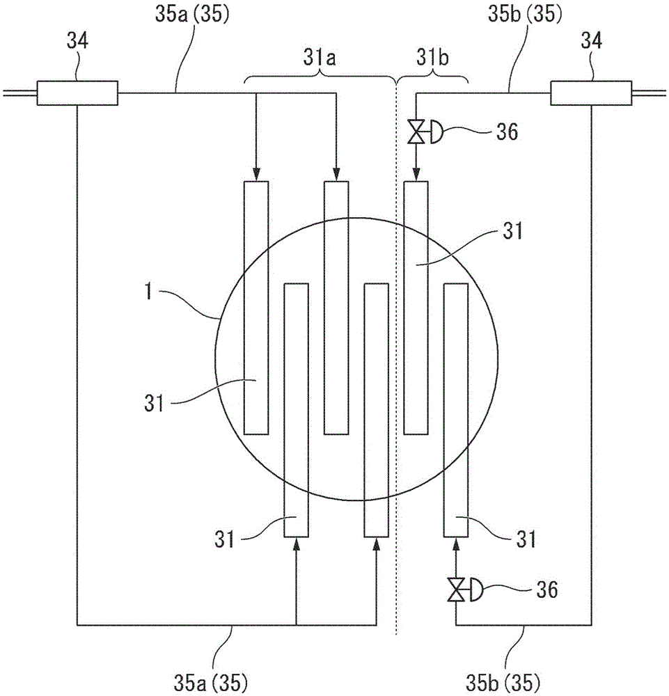
[0144] Such as Figure 11 As shown, the air diffuser 30B (combustion air supply device) of the fluidized bed sludge incinerator of this embodiment has: a dispersion plate 43 filled with a sand layer S above; and a wind box provided below the dispersion plate 43 44. The wind box 44 is an introduction part of combustion air, and the sand layer S and the wind box 44 are separated by the dispersion plate 43 .

[0145] A plurality of air supply holes 45 are formed in the diffuser plate 43 . Although not shown in the figure, the air supply hole 45 penetrates the entire surface of the distribution plate 43 . A combustion air nozzle 4...


PUM


Abstract

The present invention provides a fluidized bed type sludge incinerator (100) having an incinerator main body (1) to which sludge is supplied; a combustion air supplying device (30) supplying combustion air to a sand layer (S) arranged at the lower part of the incinerator main body (1); a N2O concentration sensor (17) measuring the N2O concentration of the combustion air discharged by the incinerator main body (1); and a control means (2) adjusting combustion air amount according to the measurement value of the N2O concentration sensor (17). The combustion air supply means (2) has a flow range regulating portion for restricting the flow range of the sand layer (S) in accordance with the combustion air amount.

Description

technical field [0001] The invention relates to a fluidized bed sludge incinerator for burning sludge and an incineration treatment method. [0002] This application claims priority from Japanese Patent Application No. 2015-017864 for which it applied on January 30, 2015, and uses the content in this invention. Background technique [0003] Nitrous oxide (hereinafter N) is known as a global warming gas 2 O) Since it has not been listed as an object of exhaust gas regulation so far, the measurement of the emission concentration and the emission concentration based on the exhaust N 2 Combustion control of O concentration. However, it is known that N 2 O produces CO 2 The warming effect is about 300 times of that, and the sewage sludge is rich in nitrogen. Therefore, due to the high content of several hundred ppm of N in the combustion exhaust 2 O, so it is desirable to minimize the N exhausted from the sewage sludge burner 2 O. [0004] Patent Document 1 describes a te...

Claims


Application Information

Patent Timeline
Patent Type & Authority Applications(China)
IPC IPC(8): F23G7/00F23G5/30
CPCF23G5/30F23G7/001Y02W10/40
Inventor 藤原雅树清水义仁长克美松寺直树松下崇伊藤隆行渡会毅
Owner MITSUBISHI HEAVY IND ENVIRONMENTAL & CHEM ENG CO LTD
Features
  • R&D
  • Intellectual Property
  • Life Sciences
  • Materials
  • Tech Scout
  • Unparalleled Data Quality
  • Higher Quality Content
  • 60% Fewer Hallucinations
Learn More