Supercharge Your Innovation With Domain-Expert AI Agents!

Primary and secondary air coupled jet system and its operation method

A technology of jet system and operation method, which is applied in combustion method, regulation of air supply, control of combustion, etc., can solve the problems of increased emission concentration and high furnace temperature, and achieves improved fuel burnout performance, reduced NOx emission concentration, and improved airflow. Effects of pressure and jet velocity

Active Publication Date: 2021-08-03
ELECTRIC POWER RES INST OF STATE GRID ZHEJIANG ELECTRIC POWER COMAPNY +1
View PDF12 Cites 0 Cited by
  • Summary
  • Abstract
  • Description
  • Claims
  • Application Information

AI Technical Summary

Problems solved by technology

Due to the enrichment of fuel in the main burner area, the furnace temperature is very high. With the further increase of oxygen content, NO x The emission concentration increased significantly, which became a difficult control point for the low-load operation of the unit

Method used


Image

  • Primary and secondary air coupled jet system and its operation method
  • Primary and secondary air coupled jet system and its operation method
  • Primary and secondary air coupled jet system and its operation method

Examples


Embodiment 1

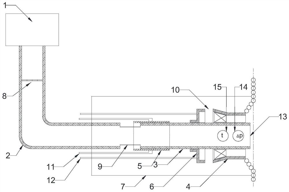
[0031] This embodiment provides a secondary air coupling jet system, such as Figure 1-2 As shown, it includes primary air main pipe 1, primary air branch pipe 2, direct current jet pipe 3, swirl jet pipe 4, direct current secondary air adjustment sleeve 5, swirl air regulating disc 6, secondary air box 7 and direct current primary Air regulating valve 8.

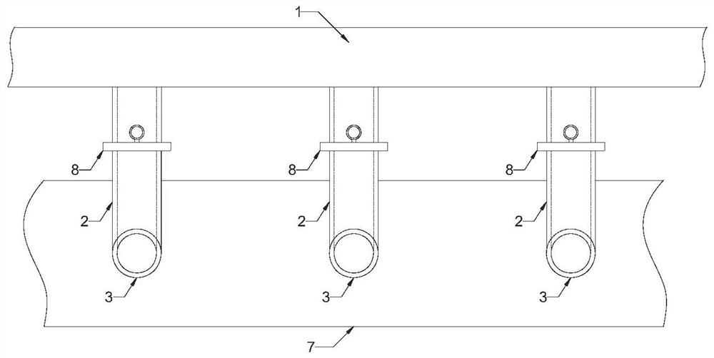
[0032] The primary air main pipe 1 is heated by primary air, and the primary air main pipe 1 is arranged along the furnace.

[0033] One end of the primary air branch pipe 2 is connected to the primary air main pipe 1, and the other end is connected to the direct current jet pipe 3; a direct current primary air regulating valve 8 is arranged on it.

[0034] Described direct current jet pipe 3, one end that is connected with direct current jet pipe 3 is direct current primary air inlet; A Pitot tube 14 and a temperature sensor 15 are installed inside the outlet 13 of the jet tube.

[0035] Said swirl jet pipe 4, one end c...

Embodiment 2

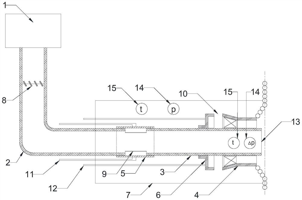
[0041] This embodiment provides the operation method of the primary-secondary air coupled jet system described in Embodiment 1, which monitors the DC jet velocity inside the outlet 13 of the DC jet tube online, and adopts different operating methods according to the magnitude of the DC jet velocity.

[0042] Such as figure 1 As shown, when the unit is running under high load conditions, the pressure of the secondary air box is high, and the DC jet velocity of the secondary air entering the DC jet pipe 3 through the DC secondary air inlet 9 is higher than the empirical airflow velocity. At this time, the DC primary air adjustment The valve 8 does not need to be opened, the direct current secondary air regulating sleeve 5 and the swirl air regulating disc 6 maintain a proper opening, and the secondary air is sprayed into the furnace from the direct current jet tube 3 and the swirl jet tube 4 respectively.

[0043] Such as figure 2 As shown, when the load of the unit decreases,...


PUM


Abstract

The invention discloses a primary-secondary air coupled jet system and an operating method thereof. Thermal power unit NO under low load condition x Emission concentration is difficult to control. The primary and secondary air coupling jet system of the present invention includes primary air main pipe, primary air branch pipe, direct current jet pipe, swirl jet pipe, direct current secondary air regulating sleeve, swirl air regulating disk and secondary air box; online monitoring of direct current The DC jet velocity inside the outlet of the jet tube, when the DC jet velocity is lower than the empirical airflow velocity, the DC primary air regulating valve and the DC secondary air regulating sleeve are coupled and adjusted through the operation method of the present invention, so that the jet flow The system transitions from a simple secondary air jet to a coupled primary and secondary air jet, increasing the airflow pressure and jet velocity of the jet system, so that the overburned air jet has stronger penetration and entrainment in the furnace, and the SOFA nozzle Improved zone fuel burnout performance, which in turn reduces the amount of combustion air in the main burner zone, which helps reduce NO x emission concentration.

Description

technical field [0001] The invention belongs to the technical field of boiler pollutant emission control, in particular to a primary and secondary air coupled jet system and an operating method thereof. Background technique [0002] Staged air supply is a simple and effective way to reduce NO x Most of the burners of large-scale thermal power units adopt the method of graded air supply. The air required for combustion is sent into the furnace in stages through multiple burner nozzles, and the part of the air that is sent into the furnace at the final stage of fuel combustion is called separated overfired air (SOFA for short). When the incompletely combusted fuel passes through the SOFA nozzle area, it is mixed with the secondary air sent into the SOFA nozzle and further combusted. [0003] Under high-load conditions, SOFA has high pressure, high speed, strong rigidity, long penetration distance in the furnace, and strong smoke extraction ability, which can give full play t...

Claims


Application Information

Patent Timeline
Patent Type & Authority Patents(China)
IPC IPC(8): F23C7/02F23L1/00F23L9/00F23N3/00
CPCF23C7/02F23L1/00F23L9/00F23N3/00
Inventor 吕洪坤张晓龙应明良胡建根
Owner ELECTRIC POWER RES INST OF STATE GRID ZHEJIANG ELECTRIC POWER COMAPNY
Features
  • R&D
  • Intellectual Property
  • Life Sciences
  • Materials
  • Tech Scout
  • Unparalleled Data Quality
  • Higher Quality Content
  • 60% Fewer Hallucinations
Learn More