Seat

a passenger seat and seat technology, applied in the field of seats, can solve the problems of putting significant pressure on the user's thighs, user discomfort during a journey, etc., and achieve the effects of reducing dead weight, reducing weight, and reducing weigh

Inactive Publication Date: 2009-10-01
TECHNN INT MANAGEMENT SERVICES
View PDF27 Cites 31 Cited by
  • Summary
  • Abstract
  • Description
  • Claims
  • Application Information

AI Technical Summary

Benefits of technology

[0021]Preferably the seat further comprises one or more inflatable cushions for supporting a user in use. The use of inflatable cushions, instead of conventional foam-filled cushions, provides several benefits. Inflatable cushions are light in weight compared to foam-filled cushions, and accordingly provide a weight saving that is particularly beneficial in aerospace applications. For example, this may enable an aeroplane to take off with a lower dead weight, or to use less fuel when flying and thereby reduce operating costs and exhaust emissions, or to carry more cargo. Additionally, inflatable cushions may be formed of materials which are significantly less flammable than foam, and which do not require an expensive fire barrier and are therefore cheaper. Inflatable cushions may also readily accommodate different users' body shapes and body weights, in contrast to the fairly narrow range of body weights and shapes that may be accommodated by conventional foam-filled cushions. Preferably the seat comprises a plurality of inflatable cushions. This provides the advantage that separate inflatable cushions may be provided to correspond with certain parts or regions of the human body, and the properties of the cushions may be tailored specifically to suit the corresponding body parts / regions. In a preferred embodiment, the seat comprises an inflatable lumbar support cushion, an inflatable ischia support cushion, an inflatable shoulder support cushion and an inflatable thigh support cushion. This list is in no way exhaustive, and other cushions may be provided for other body parts or regions as appropriate.
[0022]Preferably the or each inflatable cushion comprises a plurality of inflatable cells. By forming a cushion from a plurality of discrete inflatable cells, this provides the advantage that, if the user shifts his body weight from side to side over a cushion, all the air in the cushion is not displaced to one side (i.e. to the opposite side from where the user's body is), as could happen if the cushion were a single air pocket. Instead, by forming a cushion from a plurality of inflatable cells, if the user's body weight is shifted to one side, the air is retained in the separate cells and is not all displaced to the opposite side. Thus, this provides consistent comfortable support for the user's body, irrespective of whether the user remains relatively still or moves from side to side. Preferably the seat further comprises one or more air bellows in fluid communication with one or more of the inflatable cushions. Such air bellows may advantageously be arranged such that they become compressed as the seat reclines or moves, thereby forcing more air into the corresponding inflatable cushion(s), and thereby dynamically changing the cushioning characteristics of the seat as the seat is reclined or moved. Thus, more cushioning may be automatically provided in a certain part of the seat when the seat is inclined such that the said part of the seat supports more of the user's weight. Preferably each of a plurality of inflatable cells within an inflatable cushion is provided with a separate valve. Such valves advantageously retain air in the said cells, and prevent air from being undesirably displaced from one cell to another, for example if the user shifts his body weight from side to side. Preferably the said one or more air bellows are arranged beneath the seat pan, such that reclining of the seat pan compresses the bellow(s) and increases the air pressure in the inflatable cushions.
[0023]The seat may further comprise an air pump operable to increase the pressure in one or more bellows or inflatable cushions. This pump (which may for example be hand- or foot-operated, or mechanically or electrically operated) advantageously enables the user to increase the air pressure in the inflatable cushions / cells / bellows, thereby increasing the firmness and plumpness of the cushions according to his personal preferences. The air pump may be arranged to increase the air pressure in only a certain bellow or cushion, rather than in the entire pneumatic system. Similarly, the seat may further comprise a pressure release valve operable to decrease the pressure in one or more bellows or cushions, to enable the user to decrease the pressure to suit his preferences. The pressure release valve may be arranged to decrease the air pressure in only a certain bellow or cushion, rather than in the entire pneumatic system.
[0024]Preferably the seat comprises a first bellow in communication with one or more inflatable cushions, and a second bellow in communication with another one or more inflatable cushions. For example, as in the presently preferred embodiment, the first bellow may be in communication with the lumbar support inflatable cushion and the ischia support inflatable cushion, and the second bellow may be in communication with the shoulder support inflatable cushion and the thigh support inflatable cushion. Providing separate bellows for specific inflatable cushions or cushion regions provides the advantage that the bellows may be arranged or configured differently, in order to provide different pressure change behaviour in response to the compression of the bellows. For example, as in the presently preferred embodiment, the first bellow may be larger than the second bellow, such that compression of both bellows in unison provides a greater increase in pressure in the cushions / cells connected to the first bellow, and a smaller increase in pressure in the cushions / cells connected to the second bellow.
[0025]The seat may further comprise an armrest, the armrest comprising: a first pivot axis about which the armrest is pivotally coupled to the seat, the first pivot axis being oriented sideways out of the seat and thereby enabling upward and downward rotation of the armrest in use; and a second pivot axis oriented parallel to the longitudinal dimension of the armrest, the armrest being rotatable about the second pivot axis in use. The first pivot axis enables the armrest to be folded away alongside a seat's backrest when not in use, and then lowered down when required. The provision of the second pivot axis advantageously enables the armrest to have a relatively small thickness compared to its width when in its in-use configuration, and enables the armrest to be rotated through 90° such that it may be stowed with its wide surface adjacent the backrest, and then may be folded down from the stowed position and rotated about the second pivot axis to bring the wide surface uppermost for the user to rest their arm on. This provides a significant benefit in that the armrest occupies minimal space when stowed, occupying less space than conventional armrests which pivot about a single axis only. A further benefit is that the armrest takes up a minimum amount of swept space during its deployment from its stowed position to its in-use position, and may therefore be used in applications where space is at a premium.
[0026]Preferably the armrest further comprises extending means coupled to the second pivot axis and operable to enable the end of the armrest to be extended away from the first pivot axis. This advantageously enables the length of the armrest to be adjusted to suit users of different arm lengths and anatomical proportions. Particularly preferably the extending means comprise a shaft slideable within the armrest. Other extending means are possible, such as a gas strut or a hydraulic, pneumatic or motorised assembly, for example. Preferably the armrest has a relatively small thickness compared to its width when in its in-use configuration. Preferably the armrest is profiled to conform around a user's body when in its in-use configuration. This increases the amount of usable armrest space available to the user, without encroaching on a neighbouring passenger's space.

Problems solved by technology

Both these adjustment procedures, and in particular the reclining of the backrest, can put significant pressure on the user's thighs, and may be uncomfortable.
Additionally, with a conventional fixed horizontal seat pan, tilting the backrest backwards results in the user's body being pushed forward at the hip point and the body tending to slide away from the backrest, which creates a gap at the lower part of the back in which the back is not supported (hence the need to provide supplementary cushions on long haul flights).
More generally, a user of a passenger seat (for example, an airline seat, train seat, coach seat, bus seat, or such like) may experience discomfort during a journey.
Whilst conventional reclining seats enable the user to adjust their back angle, they do not generally enable the user to change the pressure points (i.e. the parts of the user's body which bear pressure or stress) during the journey.
As a consequence, the user may risk ailments such as deep vein thrombosis, due to the being substantially immobile for a long period of time, without being able to change the pressure points.
Further problems relate to the cushions provided on conventional passenger seats.
Conventional aircraft seat cushions are usually filled with foam, which can be relatively heavy.
Foam cushions can also be relatively flammable, and may give rise to a risk of fire or smoke during a flight.
In practice, the flammability of a foam-filled airline seat is often reduced by encasing the foam cushion in a protective fire barrier, but such fire barriers are generally made of an expensive cloth.
Conventional foam cushions can also be somewhat unaccommodating for different users' body shapes and body weights; generally a foam cushion is really only suitable for a fairly narrow range of body weights and shapes.

Method used


Image

  • Seat
  • Seat
  • Seat

Examples


second major embodiment

of Kinematic System

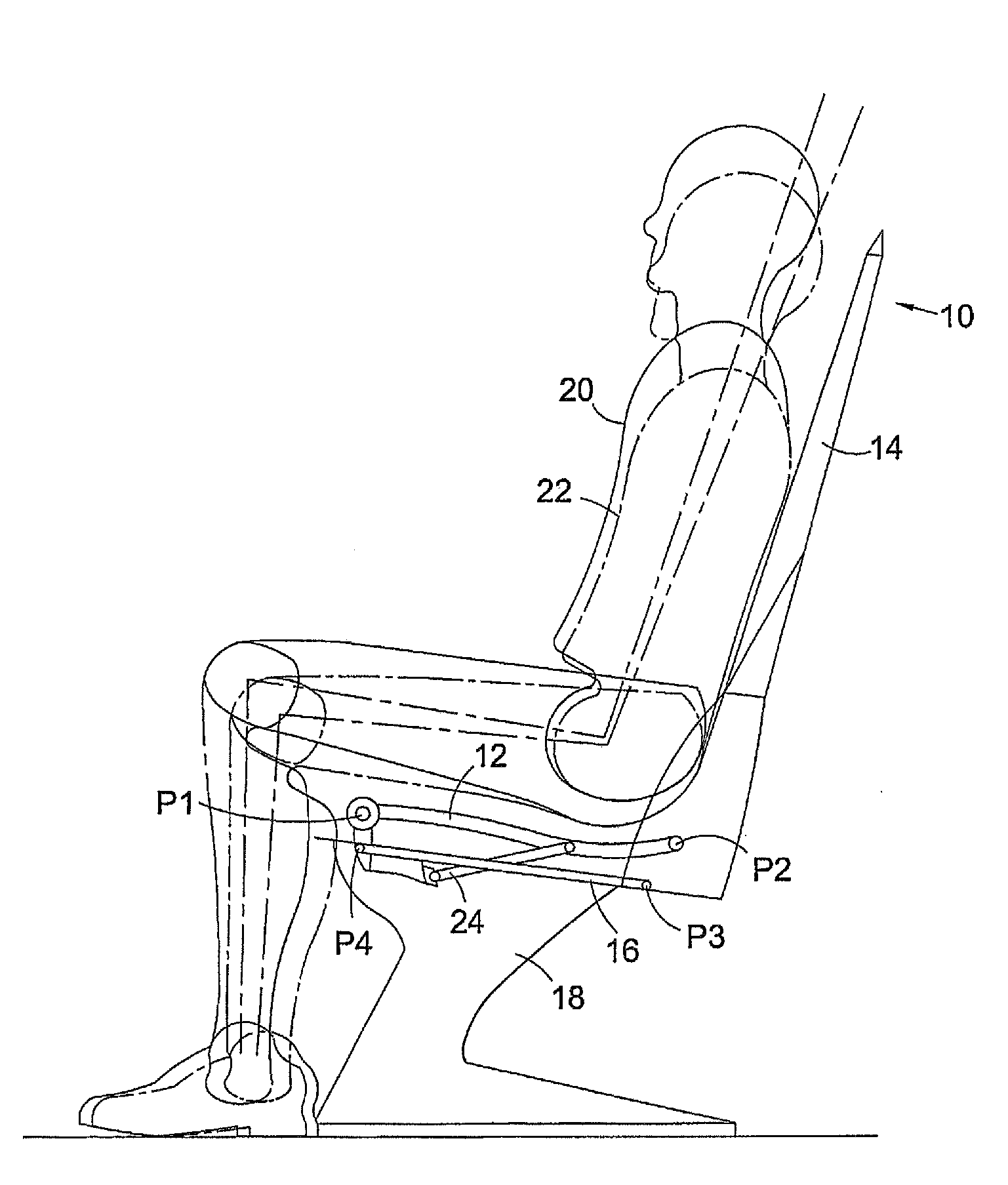
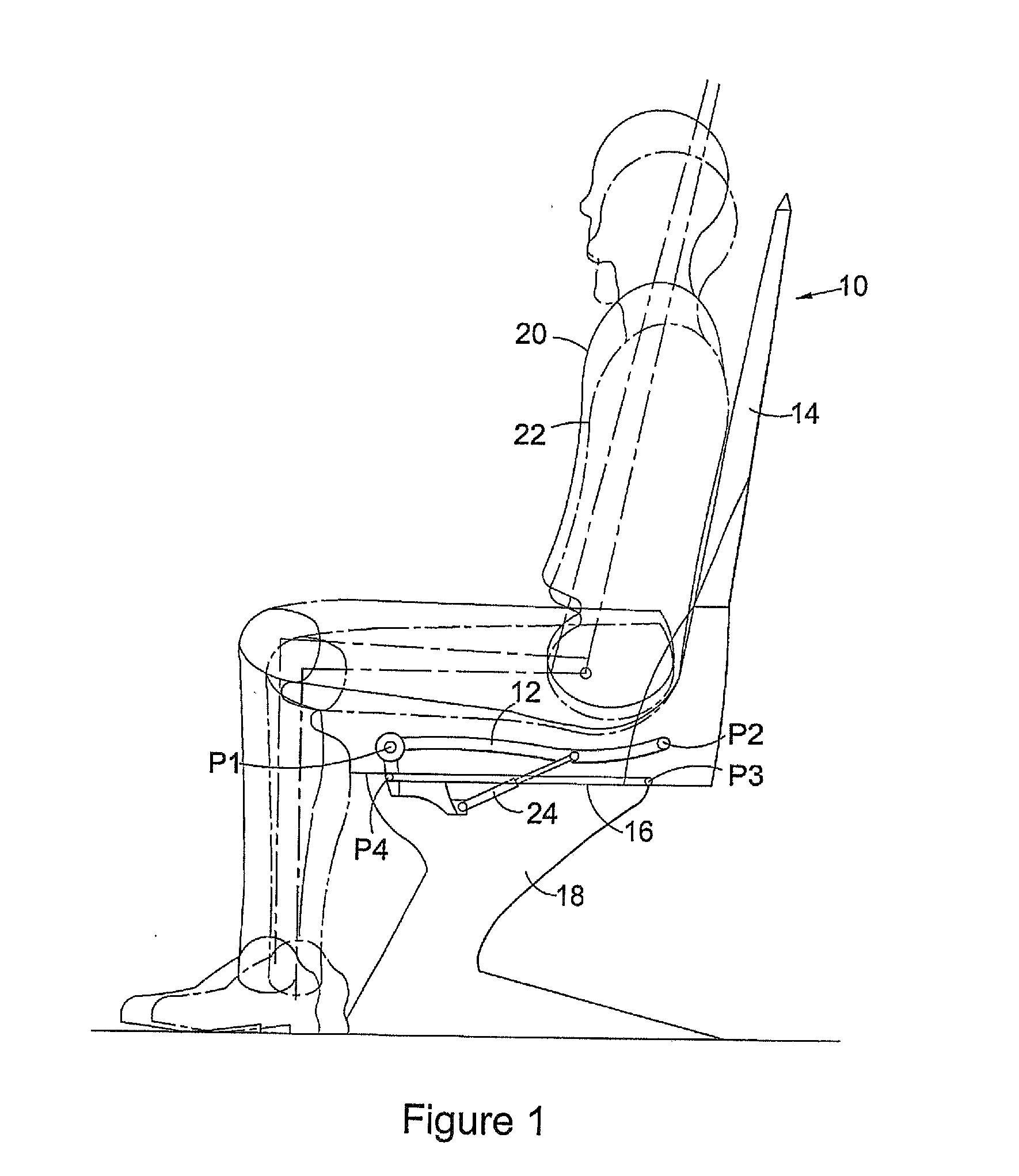
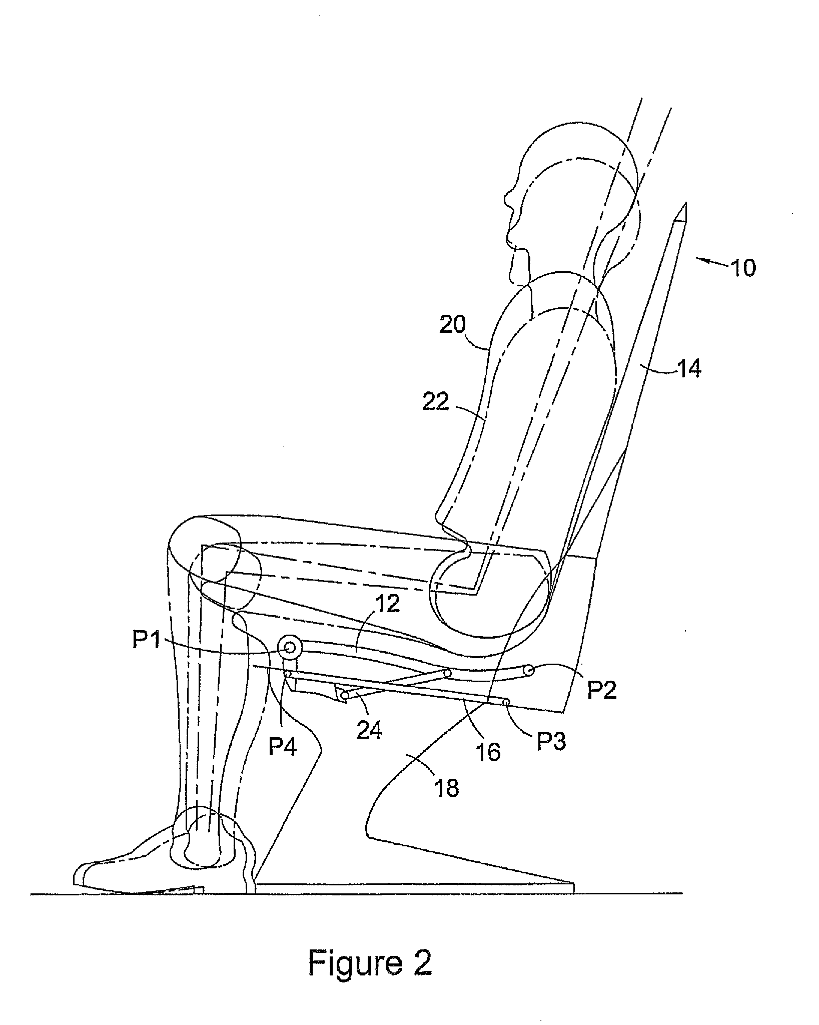
[0102]FIGS. 30 to 33 illustrate the second major embodiment of kinematic system to achieve the desired adjustability of the seat between Delta, Delta 1 and Delta 2 positions FIG. 30 shows this embodiment in its rest, delta, position with the seat pan 12 substantially horizontal / level to the floor. Again, the seat pan 12 is pivoted to the seat structure 18 at pivot axis P1 along the front edge of the seat pan 12 and again the first pivot axis P1 is static in use of the seat, remaining at the same height and position relative to the floor level of the aircraft throughout the various repositioning modes of the seats.

[0103]As with the first preferred embodiment, the backrest 14 is pivotally coupled to the rear of the seat pan 12 by a second pivot axis P2 extending across the rear of the seat pan 12. The arrangement also has a third pivot axis P3 that couples a first structural member or con rod 16 to a lower edge of the backrest 14. The opposing end of the first struc...


PUM


Abstract

A seat comprising a seat pan (12) and a support structure, wherein the seat pan (12) is pivotally coupled to the support structure (8) about a first pivot axis (pi) provided across substantially the front of the seat pan (12), such that the seat pan (12) may be pivoted about the said first pivot axis (pi) in use, and the angle of the seat pan (12) relative to the support structure (18) may thus be adjusted. The seat further comprises a backrest (14), the backrest being coupled (p2) to substantially the rear of the seat pan (p2). Also provided is pneumatic apparatus for use with a seat, comprising one or more inflatable cushions for supporting a user in use. Further provided is an armrest comprising: a first pivot axis about which the armrest may be pivotally coupled to a seat, the first pivot axis being arranged to orient sideways out of the seat and thereby enable upward and downward rotation of the armrest in use; and a second pivot axis oriented parallel to the longitudinal dimension of the armrest, the armrest being rotatable about the second pivot axis in use.

Description

[0001]This invention relates to a seat. It is particularly suitable, but not necessarily limited, for use especially in aeroplanes but also in trains, buses, coaches, or other forms of passenger transport. It is also suitable for use in offices, houses, theatres, concert halls, conference centres, hotels, and other locations.BACKGROUND TO THE INVENTION[0002]There are a wide variety of individual or mass transport passenger seats providing a variety of adjustability options and configurations to suit the user's need to change the posture of his body whilst seated. Examples of such seats include airline seats, train seats, bus seats, coach seats, and so on. Such seats may be fixed to a floor, or fixed to a frame wherein the frame is fixed to a floor. Typically, such seats are configured to offer a varying degree of fit to the user's morphology, anatomy, or change of posture. Such seats' adjustability options can include seat height adjustability from floor level, seat depth adjustabil...

Claims


Application Information

Patent Timeline
Patent Type & Authority Applications(United States)
IPC IPC(8): B64D11/06A47C1/00A47C1/02A47C1/032B60N2/02B60N2/75
CPCB60N2/1695B60N2/1814B60N2/1835B60N2/1853B60N2/23B64D11/0611B64D11/06Y02T50/46B60N2002/247B64D11/064B64D11/0646B60N2/4633B60N2/767Y02T50/40A47C1/032A47C7/467B60N2/10B60N2/18
Inventor RAYMOND, PATRICK
Owner TECHNN INT MANAGEMENT SERVICES
Why Eureka
Try Eureka