Material processing system and method

a material processing and material technology, applied in the direction of metal material coating process, electric discharge tube, coating, etc., can solve the problems of unsatisfactory accuracy with which the conventional system may be used to process work pieces, and achieve the effect of high vacuum, higher gas pressure, and high gas pressur

Inactive Publication Date: 2005-05-19
CARL ZEISS SMT GMBH +1
View PDF35 Cites 31 Cited by
  • Summary
  • Abstract
  • Description
  • Claims
  • Application Information

AI Technical Summary

Benefits of technology

[0040] Furthermore, this is an intermediate vacuum section disposed between the vacuum section comprising the electron source and the vacuum section of the processing chamber. As a result, it is possible to maintain a higher gas pressure in the vacuum section of the processing chamber than in the vacuum section comprising the electron source. The electron source requires a particularly high vacuum for its operation while reactive gases are supplied to the processing chamber which causes a higher gas pressure in the latter. It is likewise possible to provide in the vacuum section comprising the electron source still further vacuum sections separated by pressure diaphragms in order to provide an improved vacuum for the electron source itself.
[0041] Preferably, according to this aspect, the electron detector for taking the electron-microscopic images is disposed in the vacuum section. This prevents the detector from being damaged by the in most cases aggressive reactive gases which are supplied to the processing chamber.
[0042] Furthermore, a focusing lens of the electron microscope which is disposed next to the object plane is preferably disposed between the detector and the object plane. This enables a particularly small distance to be realized between the focusing lens next to the object plane and the object plane, because the electron detector need not be positioned in a space between the focusing lens next to the object plane and the object plane. Such small working distance allows a particularly fine focusing of the electron beam in the object plane.

Problems solved by technology

The conventional system was found to be unsatisfactory as regards the accuracy with which the processing of the work pieces may be carried out.

Method used


Image

  • Material processing system and method
  • Material processing system and method
  • Material processing system and method

Examples


Embodiment Construction

[0062] In the exemplary embodiments described below, components that are alike in function and structure are designated as far as possible by alike reference numerals. Therefore, to understand the features of the individual components of a specific embodiment, the descriptions of other embodiments and of the summary of the invention should be referred to.

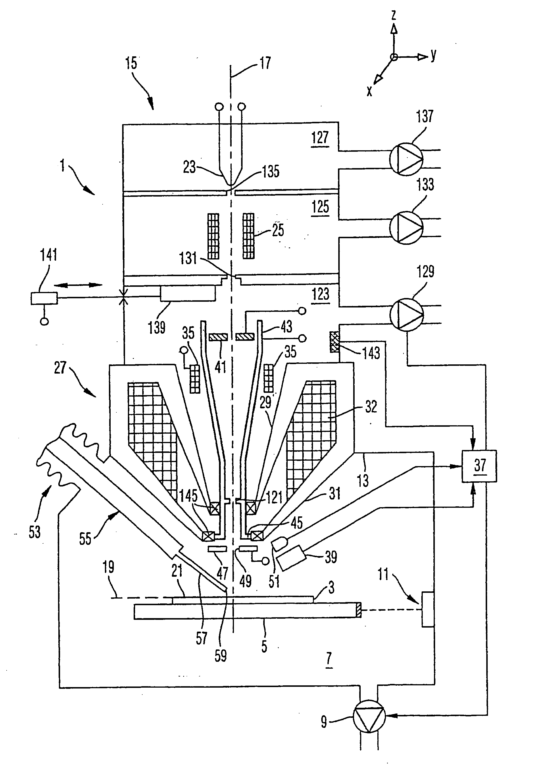
[0063]FIG. 1 schematically illustrates an embodiment of a material processing system 1 according to the invention. This system is used to process a work piece 3, namely a phase mask. This photo mask serves for use in a photolithographic process and carries structures which are photographically transferred to a radiation-sensitive layer (resist) with which a semiconductor substrate (wafer) is coated. In relation to the wavelength of the light used to transfer the structures from the mask to the semiconductor substrate, the critical dimensions of the structures are relatively small. Therefore, the structures on the mask are not merel...


PUM

PropertyMeasurementUnit
temperatureaaaaaaaaaa
distanceaaaaaaaaaa
lengthaaaaaaaaaa

Abstract

A material processing system for processing a work piece is provided. The material processing is effected by supplying a reactive gas and energetic radiation for activation of the reactive gas to a surrounding of a location of the work piece to be processed. The radiation is preferably provided by an electron microscope. An objective lens of the electron microscope is preferably disposed between a detector of the electron microscope and the work piece. A gas supply arrangement of the material processing system comprises a valve disposed spaced apart from the processing location, a gas volume between the valve and a location of emergence of the reaction gas being small. The gas supply arrangement further comprises a temperature-adjusted, especially cooled reservoir for accommodating a starting material for the reactive gas.

Description

[0001] This application is a continuation of International Application No. PCT / EP03 / 01923 filed on Feb. 25, 2003, which International Application was published by the International Bureau on Aug. 28, 2003, and which was not published in English, the entire contents of which are incorporated herein by reference. This application also claims the benefit of DE 102 08 043.7 filed on Feb. 25, 2002, the entire contents of which are incorporated herein by reference.BACKGROUND OF THE INVENTION [0002] 1. Field of the Invention [0003] The invention relates to a material processing system, a material processing method and a gas supply arrangement for the same, especially for use in methods for processing materials by material deposition from gases, such as CVD (Chemical Vapor Deposition), or material removal involving supply of reactive gases. In particular, the gas reaction resulting in a material deposition or a material removal is induced by a beam of energy which is directed to a portion o...

Claims


Application Information

Patent Timeline
Patent Type & Authority Applications(United States)
IPC IPC(8): C23C16/00
CPCH01J37/3056H01J2237/006H01J2237/31744H01J2237/166H01J2237/31732H01J2237/162
Inventor KOOPS, HANS W.P.HOFFROGGE, PETER
Owner CARL ZEISS SMT GMBH
Why Eureka
Try Eureka