Check patentability & draft patents in minutes with Patsnap Eureka AI!

Damping net tensioner

A technology of tensioning device and damping net, applied in the direction of thin plate connection, connecting member, mechanical equipment, etc., can solve the problems of uncontrollable flow, unadjustable damping net tensioning progress, sealing of rectifier section, etc., and achieves the effect of convenient installation.

Active Publication Date: 2017-10-27
北京飞擎科技有限公司
View PDF6 Cites 0 Cited by
  • Summary
  • Abstract
  • Description
  • Claims
  • Application Information

AI Technical Summary

Problems solved by technology

The fixed connection method is to directly fix the damping net on the cylinder body of the rectification section, which has the problem that the tension of the damping net cannot be adjusted and the flow cannot be controlled; the elastic connection needs to open holes in the rectification section, and there is a seal in the rectification section. And other issues

Method used


Image

  • Damping net tensioner
  • Damping net tensioner

Examples


Embodiment 1

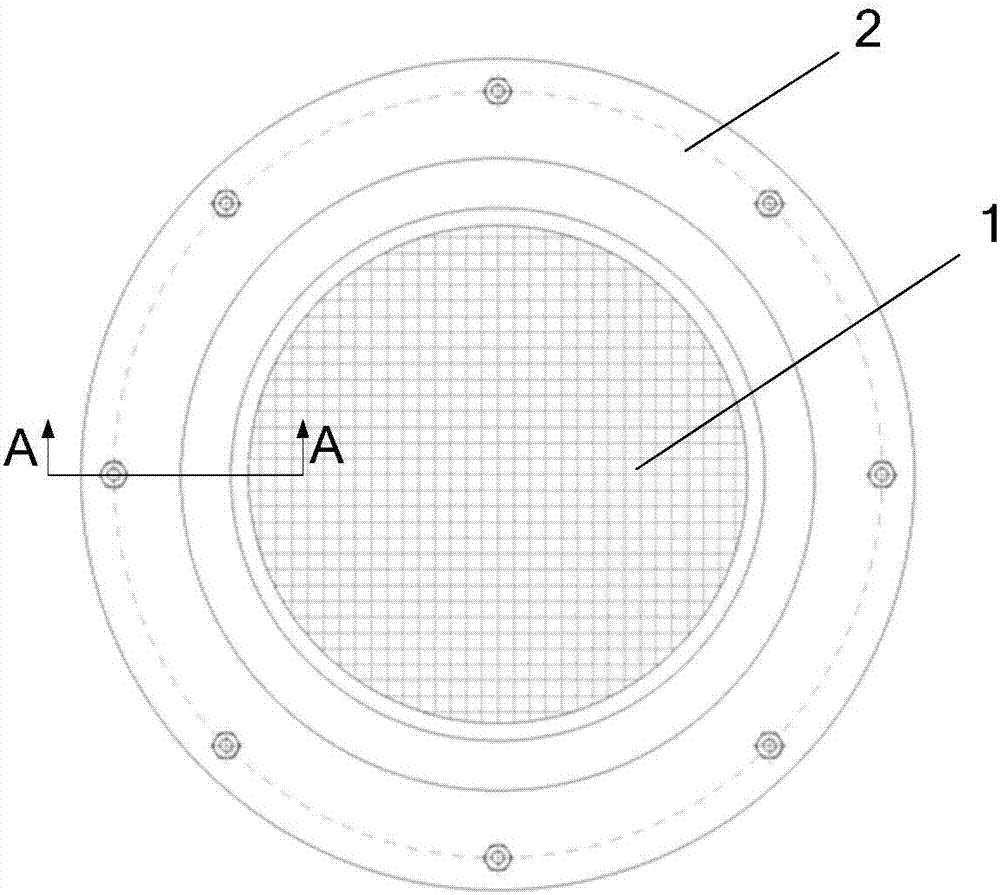
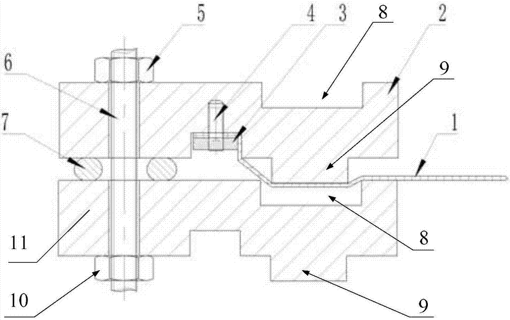
[0026] combine figure 1 and figure 2 As shown, a damping mesh tensioning device provided in Embodiment 1 of the present invention is used to tension and arrange the damping mesh in the flow field area such as the cylinder body, so as to form a rectification effect on the flow field in the area; the device includes The first compression ring 2 and the second compression ring 11 arranged concentrically, the shapes of the first compression ring 2 and the second compression ring 11 are adapted to the cross-sectional shape of the flow field, that is, if the cylinder is a cylinder Shaped channel, then the first compression ring 2 and the second compression ring 11 are circular rings; the opposite side of the first compression ring 2 and the second compression ring 11 extends circumferentially with an annular protrusion 9, and the second compression ring 2 The side of the compression ring 11 opposite to the first compression ring 2 is circumferentially extended with an annular groo...

Embodiment 2

[0033] A damping net tensioning device provided in Embodiment 2 differs from Embodiment 1 in that:

[0034] The clamping structure includes bolts, and the screw rod 6 is axially passed through the first compression ring 2 and the second compression ring 11; Side; a third nut is installed on the bolt and on the side of the second compression ring 11 opposite to the first compression ring 2 .

[0035]It can be seen that in this embodiment, the screw rod 6 and the first nut 5 in the first embodiment are integrated into one bolt, because in order to realize the adjustment of the clamping force between the first compression ring 2 and the second compression ring 11, only the One nut can be adjusted, and the other nut can be fixed, which is equivalent to a bolt structure, thereby simplifying the structure and making the installation operation more convenient.

[0036] The difference between the second embodiment and the first embodiment is only that the screw rod 6 and the first nu...

Embodiment 3

[0038] The damping net tensioning device provided in Embodiment 3 belongs to the same general inventive concept as Embodiment 1 and Embodiment 2, specifically:

[0039] It includes a plurality of third compression rings arranged concentrically, one side of the third compression ring is circumferentially extended with an annular protrusion 9, and the other side of the third compression ring is corresponding to the annular protrusion 9 An annular groove 8 is extended circumferentially at the position of the third compression ring, so that the annular protrusion 9 and the annular groove 8 on two adjacent third compression rings form a mutual insertion relationship; On one side or the other side, and on the outer side of the annular protrusion 9 and the annular groove 8, a fixed structure is provided, and the fixed structure is used to fix the edge of the tensioned net 1; between every two adjacent third compression rings Elastic members 7 are evenly spaced between them, and a cla...


PUM


Abstract

The invention relates to the technical field of flow field test, and provides a damping net tensioning device. The device comprises a first clamp ring and a second clamp ring which is coaxial with the first clamp ring; a ring-shaped bulge is circumferentially arranged on one side, opposite to the second clamp ring, of the first clamp in an extension manner; a ring-shaped groove is formed in one side, opposite to the first clamp ring, of the second clamp ring in an extension manner; the ring-shaped bulge is matched with the ring-shaped groove in a pluggable manner; a fixing structure is arranged on the first clamp ring or the second clamp ring and located outside the ring-shaped bulge and the ring-shaped groove; the fixing structure is used for fixing the edge of a tensioned net; elastic components are alternately arranged between the first clamp ring and the second clamp ring; a clamping structure is connected between the first clamp ring and the second clamp ring. Through adjusting the clamping force of the clamping structure, the adjustment of the dragging degree of the tensioned net is realized, so that the adjustment of the tensioning degree of the tensioned net is realized; according to the device, a hole does not need to be formed in a rectification section, so that no sealing problem exists and the mounting is convenient.

Description

technical field [0001] The invention relates to the technical field of flow field testing, in particular to a damping net tensioning device. Background technique [0002] In the flow field test of a small-sized channel, the incoming air flow is very turbulent, and the velocity distribution of the flow field is very uneven. In order to study the flow effect under the condition of a uniform flow field, it is usually necessary to rectify the incoming flow. One of the main devices for rectification is the damping net. Let the incoming flow pass through the tensioned damping net to achieve the effect of rectification, and the tension of the damping net has an important impact on the uniformity of the flow field. [0003] The existing fixing structure of the damping net mainly includes a fixed device and an elastic connection device. The fixed connection method is to directly fix the damping net on the cylinder body of the rectification section, which has the problem that the ten...

Claims


Application Information

Patent Timeline
Patent Type & Authority Patents(China)
IPC IPC(8): F16B5/01F16B5/02F16B5/06
CPCF16B5/01F16B5/0291F16B5/06
Inventor 陶智李海旺由儒全魏宽
Owner 北京飞擎科技有限公司
Features
  • R&D
  • Intellectual Property
  • Life Sciences
  • Materials
  • Tech Scout
  • Unparalleled Data Quality
  • Higher Quality Content
  • 60% Fewer Hallucinations
Learn More