Adaptive tuning vibration table and detection method
A vibrating table and self-adaptive technology, applied in the field of instrument detection, can solve the problems of inability to monitor the vibration effect in real time and the inability of the instrument vibrating table to adaptively control the vibration frequency, so as to achieve the effect of real-time monitoring of the vibration effect.
- Summary
- Abstract
- Description
- Claims
- Application Information
AI Technical Summary
Problems solved by technology
Method used
Image
Examples
specific Embodiment approach 1
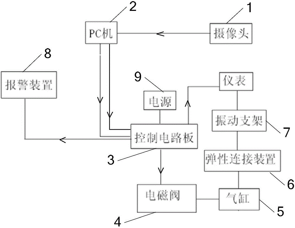
[0014] Specific implementation mode one: see figure 1 Describe this embodiment, a kind of self-adaptive tuning vibrating table described in this embodiment, it comprises camera 1, PC machine 2, control circuit board 3, solenoid valve 4, cylinder 5, elastic connection device 6, vibrating support 7 and alarm device 8;
[0015] The vibration support 7 is fixed on the elastic connecting device 6, and the vibration support 7 is used to fix the instrument to be tested;
[0016] The camera 1 is used to collect image information of the meter under test in real time, the data signal output end of the camera 1 is connected to the data signal input end of the PC 2, and the control signal output end of the PC 2 is connected to the control signal input end of the control circuit board 3 , the data signal output end of PC 2 is connected with the data signal input end of control circuit board 3;
[0017] The alarm signal output end of the control circuit board 3 is connected with the alarm...
specific Embodiment approach 2
[0022] Specific implementation mode two: see figure 1 This embodiment is described. The difference between this embodiment and the self-adaptive tuning vibrating table described in Embodiment 1 is that it also includes a power supply 9 for providing electric energy to the control circuit board 3 .
specific Embodiment approach 3
[0023] Specific embodiment three: this embodiment adopts the detection method realized by an adaptive tuning vibration table described in specific embodiment one, and the method includes the following steps:
[0024] Step 1: The instrument to be tested remains in a static state, the camera 1 collects the vibration image of the instrument to be tested in real time, and the PC 2 sends a low-frequency signal to the control circuit board 3, and the low-frequency signal is sent from the starting value at intervals of 0.05Hz to the final value , while the control circuit board 3 sends data signals to the instrument under test, so that the instrument under test is in a normal working state;
[0025] Step 2: The control circuit board 3 outputs a control signal to control the solenoid valve 4 to close, so that the cylinder 5 starts to work, and the movement of the cylinder 5 sequentially drives the elastic connection device 6 and the vibrating support 7 to move together, so that the ins...
PUM
 Abstract
Description
Claims
Application Information
 - R&D
- Intellectual Property
- Life Sciences
- Materials
- Tech Scout
- Unparalleled Data Quality
- Higher Quality Content
- 60% Fewer Hallucinations
Browse by: Latest US Patents, China's latest patents, Technical Efficacy Thesaurus, Application Domain, Technology Topic, Popular Technical Reports.
© 2025 PatSnap. All rights reserved.Legal|Privacy policy|Modern Slavery Act Transparency Statement|Sitemap|About US| Contact US: help@patsnap.com

