
Display device

A display device and display panel technology, which is applied to identification devices, nonlinear optics, instruments, etc., can solve the problems of narrow frame design and large unilateral width of difficult-to-display devices, and achieves increasing effective sticking area, reducing frame width, The effect of improving the reliability of pasting

Inactive Publication Date: 2016-08-17
BOE TECH GRP CO LTD +1
View PDF5 Cites 21 Cited by
  • Summary
  • Abstract
  • Description
  • Claims
  • Application Information

AI Technical Summary

Problems solved by technology

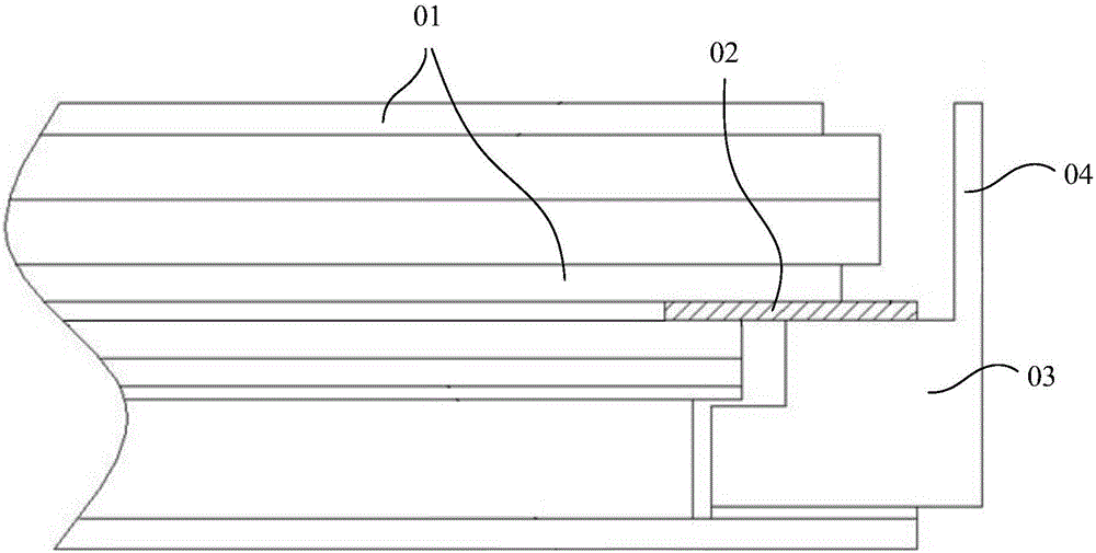
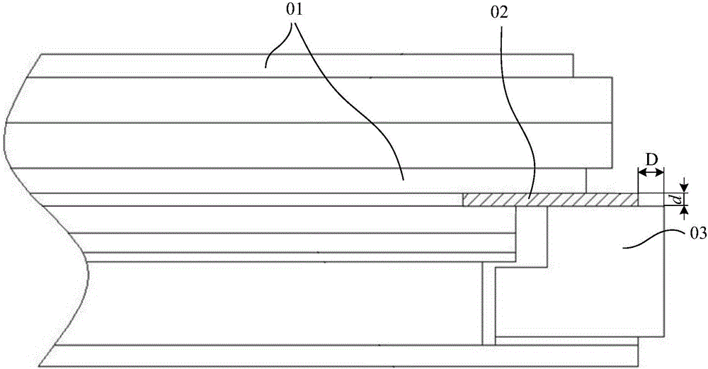
However, in order to increase the bonding area between the light-shielding tape 02 and the plastic frame 03, and to prevent the outer edge of the light-shielding tape 02 protruding from the outer edge of the plastic frame 03 and affect the subsequent installation and positioning, ideally, the light-shielding tape 02 The outer edge should be aligned with the outer edge of the plastic frame 03, but due to the limitations of the processing of the light-shielding tape 02 and the alignment accuracy of the paste, the outer edge of the light-shielding tape 02 is usually unavoidable beyond the outer edge of the plastic frame 03, so the plastic frame 03 It needs to be designed wider to reserve a certain distance D between the outer edge of the light-shielding tape 02 and the outer edge of the plastic frame 03, and this reserved distance D is usually greater than the thickness d of the light-shielding tape 02, so the width of one side of the plastic frame 03 is still Larger, making it difficult to further realize the narrow frame design of the display device

Method used


Image

  • Display device
  • Display device
  • Display device

Examples


Embodiment Construction

[0023] The following will clearly and completely describe the technical solutions in the embodiments of the present invention with reference to the accompanying drawings in the embodiments of the present invention. Obviously, the described embodiments are only some, not all, embodiments of the present invention. Based on the embodiments of the present invention, all other embodiments obtained by persons of ordinary skill in the art without making creative efforts belong to the protection scope of the present invention.

[0024] In describing the present invention, it is to be understood that the terms "center", "upper", "lower", "front", "rear", "left", "right", "vertical", "horizontal", The orientations or positional relationships indicated by "top", "bottom", "inner", "outer", etc. are based on the orientations or positional relationships shown in the drawings, and are only for the convenience of describing the present invention and simplifying the description, rather than in...


PUM


Abstract

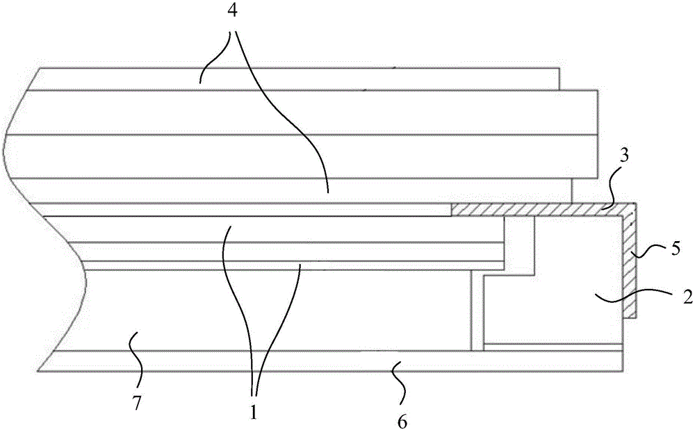
The invention discloses a display device and relates to the technical field of display devices. The invention is invented to solve the problem that it is difficult to further reduce the width of the frame on the basis of the narrow frame backlight of the display device in the prior art. The display device of the present invention includes: an optical film layer; a plastic frame, the plastic frame is arranged around the edge of the optical film layer; a double-sided light-shielding tape, one side of the double-sided light-shielding tape is bonded to the A circle of the edge of the upper surface of the optical film layer and a circle of the upper surface of the plastic frame, the part of the double-sided light-shielding tape that exceeds the outer edge of the plastic frame is bent to form a bent part, and the bent part is adhered to the plastic frame. On the outer wall of the plastic frame, and there is no adhesive layer on the surface of the bent portion away from the plastic frame; for the display panel, the edge of the lower surface of the display panel is bonded to the other side of the double-sided light-shielding tape side. The display device of the present invention can be used in mobile phones.

Description

technical field [0001] The present invention relates to the technical field of display devices, in particular to a display device. Background technique [0002] In order to meet people's demand for narrow bezel display devices, the bezels of display devices are becoming narrower and narrower. In display devices, the width of the plastic frame is an important factor affecting the width of the frame, and the cooperation between the light-shielding tape and the plastic frame determines the The width of the glue frame. [0003] example, figure 1 It is a matching structure between the light-shielding tape and the plastic frame in the prior art, such as figure 1 As shown, the display panel 01 and the plastic frame 03 are fixed and bonded by the light-shielding tape 02. In order to protect the display panel 01, the outer edge of the plastic frame 03 is provided with a retaining wall 04, and the processing and pasting alignment of the light-shielding tape 02 Due to the limitation...

Claims


Application Information

Patent Timeline
IPC IPC(8): G02F1/1333G09F9/30
CPCG02F1/133308G09F9/30
Inventor 范志强金文峰翟明傅晓亮李桐
Owner BOE TECH GRP CO LTD
Learn More