Antenna structure
A technology of antenna structure and radome, which is applied in the direction of antenna, antenna coupling, antenna components, etc., can solve the problems of complex structure and cost increase of the working platform
- Summary
- Abstract
- Description
- Claims
- Application Information
AI Technical Summary
Problems solved by technology
Method used
Image
Examples
Embodiment 1
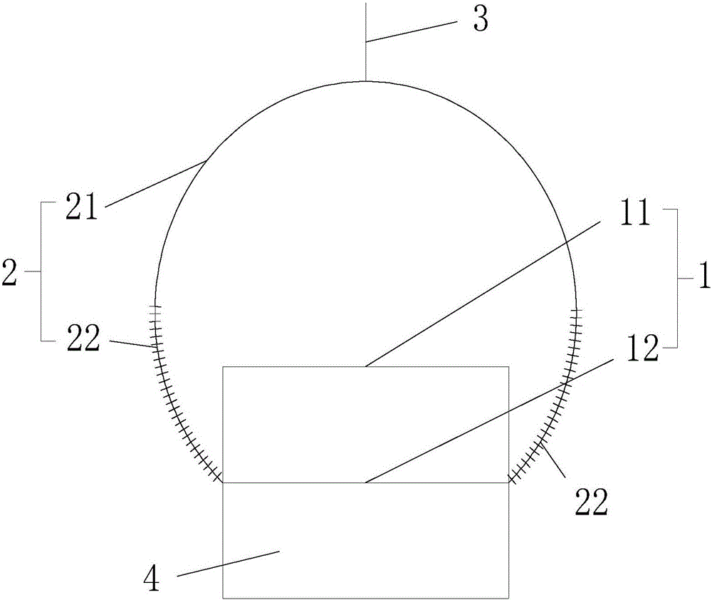
[0016] see figure 1 , the antenna pedestal has multiple layers, each layer is a group of equipment areas, and each layer of the antenna pedestal is separated by a filter partition; the top of the radome 2 is a surface-shaped filtering area, and the wave-transmitting area below the top is a ring-shaped wave-transmitting area . There can be multiple ring-shaped wave-transmitting areas according to the number of layers of the antenna seat, and each ring-shaped wave-transmitting area corresponds to at least one group of equipment areas.
[0017] The top of the above-mentioned radome 2 corresponds to the uppermost equipment area. In order to ensure the filtering function of the topmost layer of the radome 2, it cannot be ring-shaped, and the top also needs to have a filtering function, so the filtering area on the top is surface-shaped. Of course, the shape of the surface is based on the shape of the radome 2. For example, when the radome 2 is spherical, the top is a curved surfac...
Embodiment 2
[0024] The antenna pedestal has multiple groups facing different equipment areas, and each group of equipment areas is separated by the filter partition; the radome 2 has a plurality of strip-shaped wave-transmitting areas corresponding to each group of the equipment areas.
[0025] For example, the equipment area is on the same floor and is divided into four parts. Looking at the four parts from above, they can be called upper left, upper right, lower left, and lower right. It is divided into four parts, each part corresponds to an equipment area, and each filtering area is strip-shaped, and the strip-shaped filtering areas are connected in pairs to form a completed radome 2, which is set outside the equipment area.
Embodiment 3
[0027] The antenna pedestal has multiple layers similar to that in Embodiment 1, and similar to Embodiment 2 in each layer, there are multiple groups facing different equipment areas. Of course, each layer of the antenna pedestal is separated by the filtering partition, and each group of equipment areas is separated by the filtering partition; the radome 2 has a plurality of block-shaped wave-transmitting areas corresponding to each group of the equipment area.
[0028] It can be understood that multiple layers are arranged parallel to the equipment area in Embodiment 2, and the radome 2 also adjusts the distribution shape of the filtering area accordingly to meet the corresponding equipment area.
[0029] It should be understood that the above three embodiments exemplarily illustrate the installation method of the device 1. The filtering area of the radome 2 is set corresponding to the device 1, and the specific shape of the filtering area is also determined according to the...
PUM
| Property | Measurement | Unit |
|---|---|---|
| Cone angle | aaaaa | aaaaa |
Abstract
Description
Claims
Application Information
 - R&D Engineer
- R&D Manager
- IP Professional
- Industry Leading Data Capabilities
- Powerful AI technology
- Patent DNA Extraction
Browse by: Latest US Patents, China's latest patents, Technical Efficacy Thesaurus, Application Domain, Technology Topic, Popular Technical Reports.
© 2024 PatSnap. All rights reserved.Legal|Privacy policy|Modern Slavery Act Transparency Statement|Sitemap|About US| Contact US: help@patsnap.com


