antenna structure

A technology of antenna structure and radome, which is applied in the direction of antenna, antenna coupling, antenna parts, etc., can solve the problems of cost increase and complex structure of working platform

Active Publication Date: 2019-04-26
CETC OCEAN INFORMATION CO LTD +1
View PDF6 Cites 0 Cited by
  • Summary
  • Abstract
  • Description
  • Claims
  • Application Information

AI Technical Summary

Problems solved by technology

[0002] The current radar and communication equipment work in different frequency bands, and when the platform is installed and used, they are packaged in independent radome respectively. If multiple devices need to work together at the same time, then it is necessary to set up multiple independent working platforms , install the radome separately, which makes the structure of the working platform complicated and the cost increased

Method used


Image

  • antenna structure
  • antenna structure

Examples


Embodiment 1

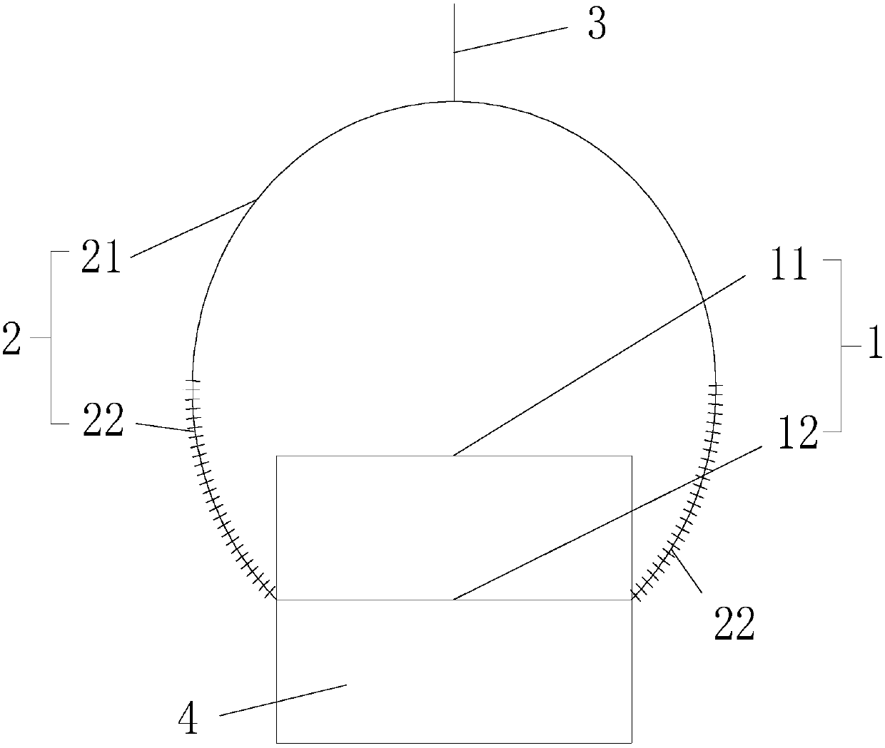
[0016] see figure 1 , the antenna pedestal has multiple layers, each layer is a group of equipment areas, and each layer of the antenna pedestal is separated by a filter partition; the top of the radome 2 is a surface-shaped filtering area, and the wave-transmitting area below the top is a ring-shaped wave-transmitting area . There can be multiple ring-shaped wave-transmitting areas according to the number of layers of the antenna seat, and each ring-shaped wave-transmitting area corresponds to at least one group of equipment areas.

[0017] The top of the above-mentioned radome 2 corresponds to the uppermost equipment area. In order to ensure the filtering function of the topmost layer of the radome 2, it cannot be ring-shaped, and the top also needs to have a filtering function, so the filtering area on the top is surface-shaped. Of course, the shape of the surface is based on the shape of the radome 2. For example, when the radome 2 is spherical, the top is a curved surfac...

Embodiment 2

[0024] The antenna pedestal has multiple groups facing different equipment areas, and each group of equipment areas is separated by the filter partition; the radome 2 has a plurality of strip-shaped wave-transmitting areas corresponding to each group of the equipment areas.

[0025] For example, the equipment area is on the same floor and is divided into four parts. Looking at the four parts from above, they can be called upper left, upper right, lower left, and lower right. It is divided into four parts, each part corresponds to an equipment area, and each filtering area is strip-shaped, and the strip-shaped filtering areas are connected in pairs to form a completed radome 2, which is set outside the equipment area.

Embodiment 3

[0027] The antenna pedestal has multiple layers similar to that in Embodiment 1, and similar to Embodiment 2 in each layer, there are multiple groups facing different equipment areas. Of course, each layer of the antenna pedestal is separated by the filtering partition, and each group of equipment areas is separated by the filtering partition; the radome 2 has a plurality of block-shaped wave-transmitting areas corresponding to each group of the equipment area.

[0028] It can be understood that multiple layers are arranged parallel to the equipment area in Embodiment 2, and the radome 2 also adjusts the distribution shape of the filter area accordingly to meet the corresponding equipment area.

[0029] It should be understood that the above three embodiments exemplarily illustrate the installation method of the device 1. The filtering area of ​​the radome 2 is set corresponding to the device 1, and the specific shape of the filtering area is also determined according to the sh...


PUM


Abstract

The invention discloses an antenna structure. The antenna structure comprises an antenna pedestal and a radome, wherein the antenna pedestal is provided with multiple equipment areas, each equipment area is used for placing equipment, and filtering partitions are arranged between equipment areas; and the radome covers the antenna pedestal, the radome is divided into multiple wave-transmitting areas, each wave-transmitting area is corresponding to at least one equipment area, and each wave-transmitting area has an independent wave-transmitting coefficient. There are multiple equipment areas so that multiple pieces of equipment can be installed. At the same time, an installation area corresponding to the radome is provided with the multiple wave-transmitting areas with independent wave-transmitting coefficients, such that equipment at different frequency ranges, such as radars, communication devices and the like can share one radome, yet signals are not mutually affected.

Description

technical field [0001] The present disclosure generally relates to the field of electrical components, in particular to an antenna, and in particular to an antenna structure. Background technique [0002] The current radar and communication equipment work in different frequency bands, and when the platform is installed and used, they are packaged in independent radome respectively. If multiple devices need to work together at the same time, then it is necessary to set up multiple independent working platforms , Install the radome separately, which makes the structure of the working platform complicated and the cost increased. Contents of the invention [0003] In view of the above-mentioned defects or deficiencies in the prior art, it is desired to provide an antenna structure, including: an antenna base and a radome, wherein the antenna base has multiple sets of equipment areas, and each set of equipment areas is used to place equipment, and , a filter partition is provi...

Claims


Application Information

Patent Timeline
Patent Type & Authority Patents(China)
IPC IPC(8): H01Q1/42H01Q1/52H01Q1/22
CPCH01Q1/22H01Q1/42H01Q1/521
Inventor 梁新张立伟余昆郭明瑞张一李立李玉辉李溢涵徐存良马腾刘泥
Owner CETC OCEAN INFORMATION CO LTD
Why Eureka
Try Eureka