Stable supporting device for bridge

A support device and stability technology, which is applied in the field of bridge stability support devices, can solve the problems of triangular bracket damage, long weld seam, poor support frame stability, etc., and achieve improved stability, increased safety factor, and uniform support force Effect

Inactive Publication Date: 2016-09-07
HARBIN GONGYANG SCI & TECH CONSULTATION CO LTD
View PDF6 Cites 2 Cited by
  • Summary
  • Abstract
  • Description
  • Claims
  • Application Information

AI Technical Summary

Problems solved by technology

[0002] With the continuous development of social economy and the continuous improvement of construction level, as well as the continuous increase of vehicles, large and small bridges have been built; in bridge construction and maintenance operations, support brackets are often used; traditional support frames are more It is made of steel pipes, such as the scaffolding commonly used in construction. Due to the large number of pipe fittings in the scaffolding, it is difficult to build, the construction progress is slow, and a lot of manpower is required to complete the construction, which brings great difficulties to the construction and maintenance of bridges. This caused great trouble; although at present in the construction of bridges, large steel plates have been pre-embedded in the bridge piers, and after the triangular bracket is assembled and welded under the bridge, the single-piece hoisting is in place and welded with the pre-embedded steel plates; although this method It can overcome the shortcomings of scaffolding such as difficulty in constructio

Method used


Image

  • Stable supporting device for bridge
  • Stable supporting device for bridge
  • Stable supporting device for bridge

Examples


Embodiment Construction

[0014] The following will clearly and completely describe the technical solutions in the embodiments of the present invention with reference to the accompanying drawings in the embodiments of the present invention. Obviously, the described embodiments are only some, not all, embodiments of the present invention. Based on the embodiments of the present invention, all other embodiments obtained by persons of ordinary skill in the art without making creative efforts belong to the protection scope of the present invention.

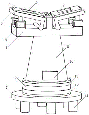
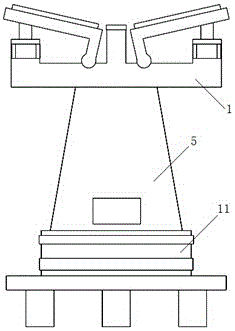
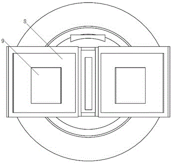
[0015] see Figure 1-3 , the present invention provides a technical solution: including a support horizontal plate 1; a support block 2 is fixedly connected in the middle of the support horizontal plate 1; side support plates 3 are symmetrically installed on both sides of the support block 2; One end of the plate 3 is rotationally connected with the support horizontal plate 1 through a pin; four hydraulic supports 4 are evenly installed on the upper end surfac...


PUM


Abstract

The invention discloses a stable supporting device for a bridge. The stable supporting device comprises a supporting transverse plate. A supporting block is fixedly connected to the middle of the supporting transverse plate. Side supporting plates are symmetrically installed on the two sides of the supporting block. One end of each side supporting plate is rotationally connected with the supporting transverse plate through a pin shaft. Four hydraulic brackets are uniformly installed on the upper end surface of the supporting transverse plate. The upper end surfaces of the hydraulic brackets are connected with the lower end surfaces of the side supporting plates. The lower end surface of the supporting transverse plate is connected with a damping supporting body through a supporting platform. A bottom plate is fixedly connected with the lower end surface of the damping supporting body. Rubber pads are arranged on the upper end surfaces of the side supporting plates and the upper end surface of the supporting block. Pressure sensors are embedded in the upper end surfaces of the rubber pads. According to the stable supporting device for the bridge, the drawbacks that a traditional supporting frame cannot be used repeatedly and is inconvenient to assemble and disassemble are overcome; the stable supporting device can be adjusted according to the bottom surface slope of the bridge, so that the supporting force is more uniform, and certain damping capacity is achieved; and the supporting intensity can be measured in real time so as to improve the safety coefficient.

Description

technical field [0001] The invention relates to the technical field of bridge support, in particular to a bridge stability support device. Background technique [0002] With the continuous development of social economy and the continuous improvement of construction level, as well as the continuous increase of vehicles, large and small bridges have been built; in bridge construction and maintenance operations, support brackets are often used; traditional support frames are more It is made of steel pipes, such as scaffolding commonly used in construction. Due to the large number of pipe fittings in the scaffolding, it is difficult to build, the construction progress is slow, and a lot of manpower is required to complete the construction, which brings great difficulties to bridge construction and maintenance. This caused great trouble; although at present in the construction of bridges, large steel plates have been pre-embedded in the bridge piers, and after the triangular brac...

Claims


Application Information

Patent Timeline
IPC IPC(8): E01D21/00
CPCE01D21/00
Inventor 张志海
Owner HARBIN GONGYANG SCI & TECH CONSULTATION CO LTD
Why Eureka
Try Eureka