Dual-step double-precision weighing sensor
A load cell, double-precision technology, applied in the field of load cell structure design, can solve the problems of use, large error, and inability to be used as a weight scale.
- Summary
- Abstract
- Description
- Claims
- Application Information
AI Technical Summary
Problems solved by technology
Method used
Image
Examples
Embodiment 1
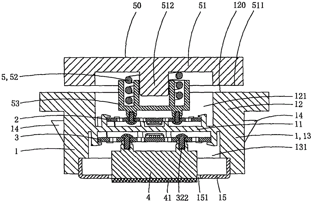
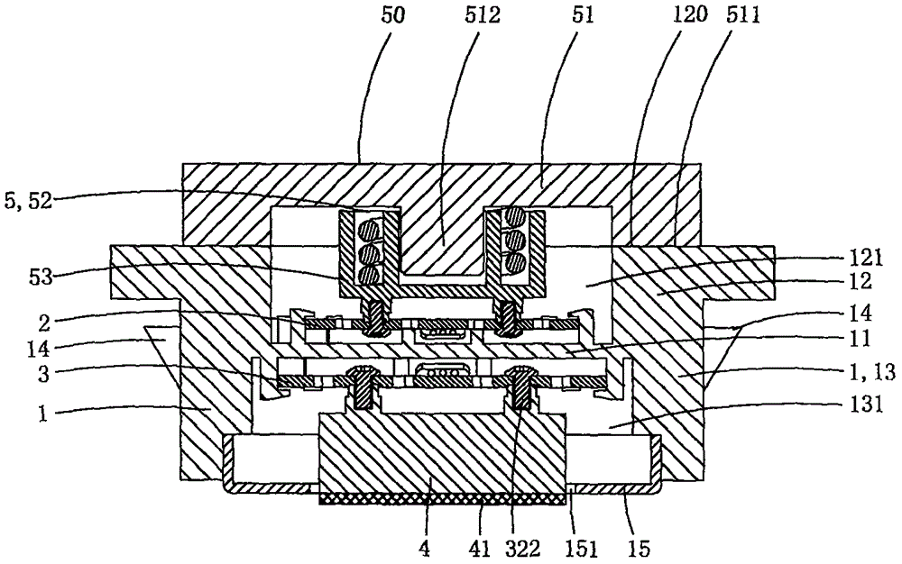
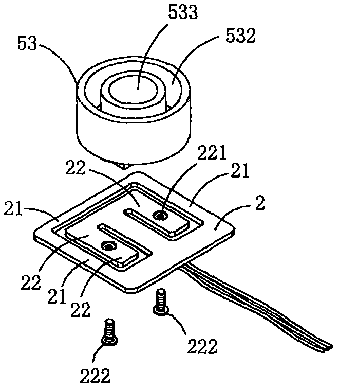
[0037] This embodiment is a double-stage double-precision load cell, see Figure 1 to Figure 6 As shown, it includes a mounting base 1 , a first precision load cell 2 , a second precision load cell 3 , a support foot 4 and an elastic support 5 .
[0038] The mounting seat is provided with a mounting plate portion 11 and a force guiding support portion 12 for transmitting the pressure received by itself to the mounting plate portion; an elastic support member, a first precision load cell, a mounting plate portion, and a second precision weighing The sensor and supporting feet are crimped and set in sequence.
[0039] The installation board part is arranged horizontally, the first card holder is arranged on the top wall of the installation board part, and the second card holder is arranged on the bottom wall. The existence of the first deck and the second deck can make the installation operation of the first precision load cell and the second precision load cell faster and more...
Embodiment 2
[0061] This embodiment is basically the same as Embodiment 1, the difference is: see Figure 7 to Figure 8 As shown, this embodiment also includes an adjustment mechanism 6 for adjusting the height of the elastic support; the outer peripheral wall of the upper support is provided with a convex stopper 513, and the outer peripheral wall of the force guiding support is provided with an external thread area 122; the adjustment mechanism includes an adjustment gland 61 and an elastic gasket 62; the upper end of the adjustment gland is provided with a ring-shaped anti-off crimping part 611, and the inner wall of the lower end is provided with an internal thread adapted to the external thread area of the force guiding support part Zone 612, the middle end is provided with a crimping surface 613; through the crimping surface, the adjusting gland crimps the elastic gasket on the top of the force-guiding support part, and the anti-off crimping part is sleeved on the upper support memb...
Embodiment 3
[0065] This embodiment is basically the same as Embodiment 2, the difference is: see Figure 9 to Figure 10 As shown, a static contact 123 is provided on the top of the force guiding support part, and a moving contact 514 adapted to the static contact is provided on the force guiding crimping part of the upper support; when the force guiding crimping part is crimped on the guide When it is on the force supporting part, the moving contact is crimped and arranged on the static contact, and the two realize electrical connection.
[0066] In practice, when the moving contact and the static contact are in electrical contact, an electrical signal is generated to the connected external central control circuit. When the central control circuit receives the signal, the second precision load cell measurement is displayed on the display When the central control circuit does not receive the signal, the data measured by the first precision load cell will be displayed on the display screen;...
PUM
 Abstract
Description
Claims
Application Information
 - R&D
- Intellectual Property
- Life Sciences
- Materials
- Tech Scout
- Unparalleled Data Quality
- Higher Quality Content
- 60% Fewer Hallucinations
Browse by: Latest US Patents, China's latest patents, Technical Efficacy Thesaurus, Application Domain, Technology Topic, Popular Technical Reports.
© 2025 PatSnap. All rights reserved.Legal|Privacy policy|Modern Slavery Act Transparency Statement|Sitemap|About US| Contact US: help@patsnap.com


