Two-precision weighing electronic scale

A double-precision, electronic scale technology, applied to the detailed information of weighing equipment, weighing, special scales, etc., can solve the problems of not being able to use as a weight scale, use, large errors, etc.

Inactive Publication Date: 2016-09-28
申俊
View PDF5 Cites 0 Cited by
  • Summary
  • Abstract
  • Description
  • Claims
  • Application Information

AI Technical Summary

Problems solved by technology

[0002] The weight electronic scales currently on the market are mainly composed of a loading board, a display screen, an adjustment button, a power module and a load cell for supporting the loading board. When the weight of the loaded object exceeds the preset value, the display screen will start to display the value. The preset value is generally 5 kg; in addition, the maximum range of this kind of weight electronic scale is generally 180 kg, and the accuracy value is only 100 grams. The error is large. Therefore, this traditional weight electronic scale can basically not be used for other purposes except for weighing, especially it cannot be used as a kitchen electronic scale.
However, the existing kitchen electronic scales have an accuracy of 1 gram or even less, but their range generally does not exceed 10 kilograms, so they cannot be used as weighing scales.

Method used


Image

  • Two-precision weighing electronic scale
  • Two-precision weighing electronic scale
  • Two-precision weighing electronic scale

Examples


Embodiment 1

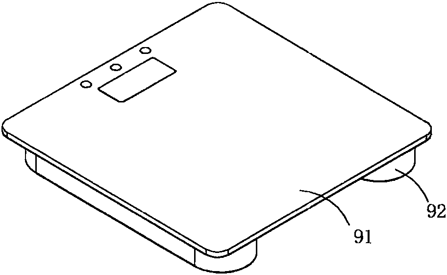
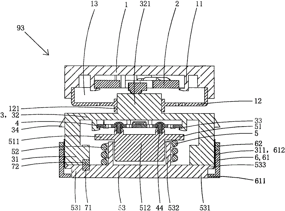
[0029] Present embodiment is a kind of double-precision weighing electronic scale, see Figure 1 to Figure 8 As shown, it includes a carrier plate 91 for placing objects to be weighed, a base 92 arranged under the carrier plate, and four double-precision load cells 93 arranged in the base for supporting the carrier plate.

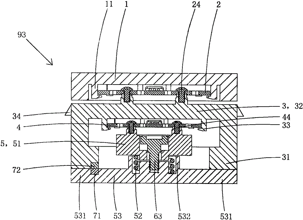
[0030] Each double-precision load cell includes a first mount 1, a first-precision load cell 2, a second mount 3, a second-precision load cell 4, and an elastic support 5 that are sequentially crimped; the elastic support includes an upper A support 51 , a threaded spring 52 and a lower support 53 . The top end of the spring abuts on the upper supporting member, and the bottom end of the elastic supporting member abuts on the lower supporting member; the lower supporting member is provided with a force guiding support portion 531 .

[0031] The bottom wall of the first mounting seat is provided with a first card seat 11, and the top wall of the first mount...

Embodiment 2

[0053] This embodiment is basically the same as the above-mentioned embodiment 1, the difference is: see Figure 9 to Figure 12As shown, the first precision load cell in this embodiment is still provided with a first fixing part, a first force-bearing deformation part, and a sensor set on the first force-bearing deformation part for detecting the deformation amount of the first force-bearing deformation part. The first resistance strain gauge; but the shape of the first precision load cell in this embodiment is similar to the reverse "G" shape, its first fixed part is similar to "C" shape, and the shape of the first force-bearing deformation part is similar to A smaller "C" shape is connected with the first fixed part to form a reverse "G" shape. The measuring range and accuracy of this first precision load cell are the same as those in Embodiment 1, and this structure can also be made by stamping, and its manufacturing process is simpler. The bottom of the first mounting sea...

Embodiment 3

[0056] This embodiment is basically the same as Embodiment 1, the difference is: see Figure 13 to Figure 16 As shown, in this embodiment, the static contact and the movable contact are no longer provided, and the annular crimping part is no longer provided on the outer peripheral wall of the upper support member, and the lower part is no longer used as a sliding column part.

[0057] In this embodiment, the center of the upper support is provided with an adjustment hole 513, and the center of the tubular boss of the lower support is also provided with a circular connecting post 534 protruding upward from the mounting plate. A connecting screw hole 535 is provided at the center of the top wall; the tubular boss and the circular connecting column form an annular limiting groove 536; the bottom end of the spring is located in the annular limiting groove and abuts against the lower supporting member, The top end of the spring abuts against the bottom wall of the upper supporting ...


PUM


Abstract

The invention discloses a two-precision weighing electronic scale. The two-precision weighing electronic scale comprises a loading plate on which an object to be weighed is placed, a base which is arranged below the loading plate, and two-precision weighing sensors which are arranged in the base to support the loading plate. Each two-precision weighing sensor comprises a first mounting seat, a first precision weighing sensor, a second mounting seat, a second precision weighing sensor and an elastic support piece, wherein the first mounting seat, the first precision weighing sensor, the second mounting seat, the second precision weighing sensor and the elastic support piece are successively crimped. Each elastic support piece comprises an upper support piece, a spring and a lower support piece. The top end of each spring abuts against an upper support piece. The bottom end of each elastic support piece abuts against a lower support piece. Each second mounting seat is provided with a force transmitting crimp part. Each lower support piece is provided with a force transmitting support part. In a free state, the force transmitting crimp part is higher than the force transmitting support part. When the second mounting seat is stressed, the second precision weighing sensor compresses the spring and drives the force transmitting crimp part to move down. When the second mounting seat is stressed to a preset extent, the force transmitting crimp part moves down to crimp the force transmitting support part. The two-precision weighing electronic scale provided by the invention has two-step continuous range, and has different precision values in the range of each step.

Description

technical field [0001] The invention belongs to the technical field of weighing instruments, and in particular relates to a double-precision weighing electronic scale. Background technique [0002] The weight electronic scales currently on the market are mainly composed of a loading board, a display screen, an adjustment button, a power module and a load cell for supporting the loading board. When the weight of the loaded object exceeds the preset value, the display screen will start to display the value. The preset value is generally 5 kg; in addition, the maximum range of this kind of weight electronic scale is generally 180 kg, and the accuracy value is only 100 grams. The error is large. Therefore, this traditional weight electronic scale can not be used for other purposes except weighing the body on weekdays, especially it cannot be used as a kitchen electronic scale. And existing kitchen electronic scale, its precision value can reach 1 gram even smaller, but its meas...

Claims


Application Information

Patent Timeline
Patent Type & Authority Applications(China)
IPC IPC(8): G01G19/44G01G19/62G01G21/08
CPCG01G19/44G01G19/62G01G21/08
Inventor 申俊
Owner 申俊
Why Eureka
Try Eureka