A flipping device for a movable stand seat

A technology of flipping device and movable stand, which can be applied to chairs, chairs in theaters, auditoriums or similar places, and household appliances, etc., can solve the problems of complicated maintenance operation and high cost, and achieve the effect of convenient operation and fast unfolding and folding.

Active Publication Date: 2019-07-16
周云翔
View PDF7 Cites 0 Cited by
  • Summary
  • Abstract
  • Description
  • Claims
  • Application Information

AI Technical Summary

Problems solved by technology

Although the motor drives the entire row of seats to flip together, one motor can only drive one row of seats to flip, and the cost of using the motor as the power source for the flip of the seats is relatively high, and the maintenance operation is complicated

Method used


Image

  • A flipping device for a movable stand seat
  • A flipping device for a movable stand seat
  • A flipping device for a movable stand seat

Examples


Embodiment 1

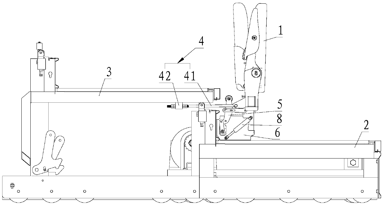
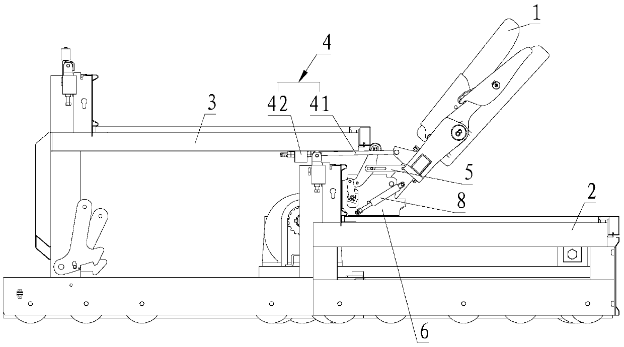
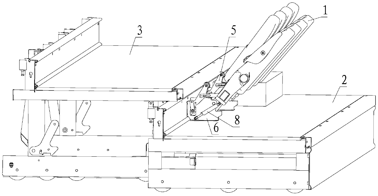
[0046] Please refer to Figure 1 to Figure 11 , Embodiment 1 of the present invention is:

[0047] A flipping device for a movable stand seat, comprising a pull rod mechanism 4 and a locking mechanism 5, one end of the pull rod mechanism 4 is slidably connected to the peripheral rear seat platform 3, and the other end is rotatably connected to the peripheral front row seat 1 , the locking mechanism 5 is located between the front seat 1 and the rear seat platform 3, the lower end of the locking mechanism 5 is frictionally connected with the bottom of the front seat 1, and the locking mechanism 5 The upper end of the position mechanism 5 is located on the sliding track of the rear seat platform 3;

[0048] The pull rod mechanism 4 includes a pull rod 41 and a slider 42, the slider 42 is provided with a first waist-shaped hole 4241 placed up and down, the right end of the pull rod 41 is rotationally connected with the front seat 1, and the pull rod The left end of 41 is passed ...

Embodiment 2

[0050] Please refer to Figure 1 to Figure 11 , the second embodiment of the present invention is:

[0051] A flipping device for a movable stand seat. On the basis of the first embodiment, the left end of the first connecting rod 51 is provided with a second waist-shaped hole 511, and the side of the second connecting rod 52 is protrudingly provided with a third A rotating shaft 521, the third rotating shaft 521 is slidingly and rotationally matched with the second waist-shaped hole 511;

[0052] The rear seat platform 3 is provided with a profile assembly 31, and the profile assembly 31 includes an inverted U-shaped upper profile 311, a U-shaped lower profile 312 and side connecting plates 313, and the inverted U-shaped upper profile 311 is connected to the U-shaped upper profile. The width of the lower profile 312 is the same, and a gap 314 is provided between the opposite side walls. The side connecting plate 313 is located at the end of the profile assembly 31, and is co...


PUM


Abstract

The invention provides a seat turnover device for a movable stand. The seat turnover device comprises a pull rod mechanism and a position clamping mechanism, wherein one end of the pull rod mechanism is connected with an externally arranged rear-row seat platform in a sliding manner, and the other end of the pull rod mechanism is movably connected with a front-row seat; the position clamping mechanism is located between the front-row seat and the rear-row seat platform; the lower end of the position clamping mechanism is in frictional connection with the bottom of the front-row seat; the upper end of the position clamping mechanism is located on the sliding track of the rear-row seat platform; owing to the pull rod mechanism, the front-row seat can be turned over when the rear-row seat platform slides backwards; the position clamping mechanism can realize frictional limitation after the front-row seat is turned over; limitation on the front-row seat from the position clamping mechanism can be removed when a rear-row seat slides forwards; linkage between movement of the rear-row seat platform and turning of the front-row seat is mechanically realized.

Description

technical field [0001] The invention relates to the technical field of flipping seats in stands, in particular to a flipping device for seats in a movable stand. Background technique [0002] At present, there are mainly two ways to turn over the seats on the event stands: one is to turn over by the operator, and only turn over one seat at a time. This operation method requires a lot of manual work and takes a very long time; The other is to turn over a row of seats at a time by manual or electric means. Although it can reduce a lot of manual operations and save a lot of time, it still requires more time and workload. For the movable grandstand that can be linked by multiple rows, it includes front seats, a front seat platform and a rear seat platform that are slidably connected to each other, and a front seat base, and the front seats are rotatably connected to the front seat platform , the front seats are rotatably connected to the front seat base, the front seat base is ...

Claims


Application Information

Patent Timeline
Patent Type & Authority Patents(China)
IPC IPC(8): A47C1/121A47C1/124
CPCA47C1/121A47C1/124
Inventor 周云翔
Owner 周云翔
Why Eureka
Try Eureka