Door body assembly of refrigeration equipment and refrigeration equipment
A refrigeration equipment and door body technology, which is applied in the field of refrigeration equipment equipped with the above-mentioned refrigeration equipment door body assembly, and can solve the problems that the refrigeration equipment door end cover cannot be shared, less materials are borrowed, and the cost of molds is increased.
- Summary
- Abstract
- Description
- Claims
- Application Information
AI Technical Summary
Problems solved by technology
Method used
Image

Examples
Embodiment 1
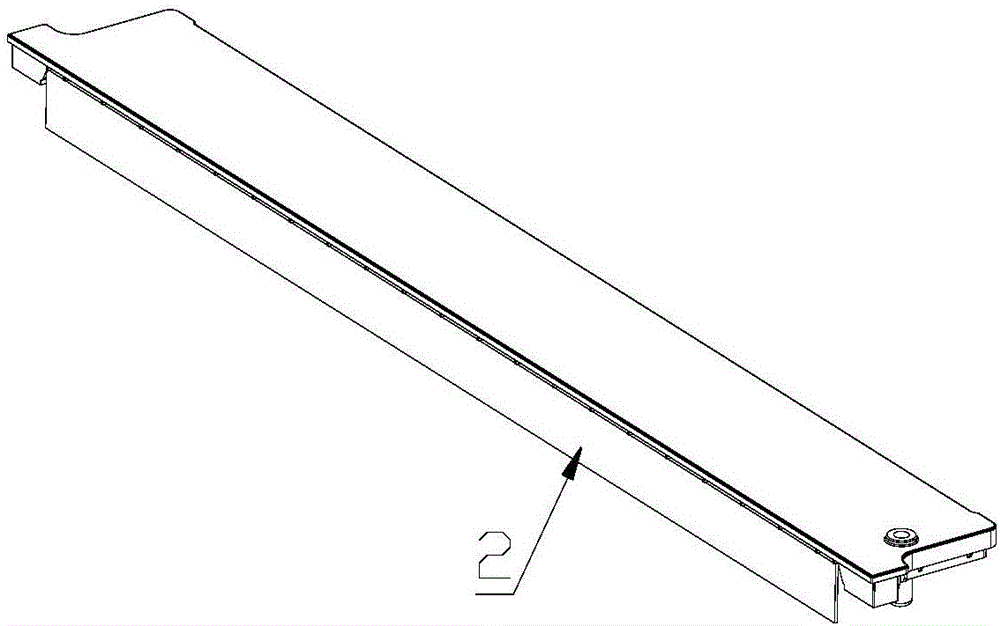
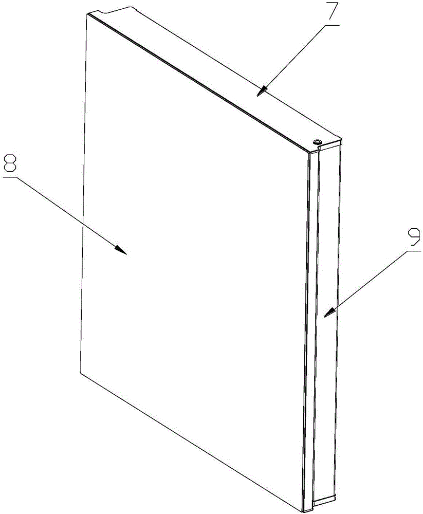
[0045] like figure 1 , 8, 9, 10, 13 and 14, the door body assembly of a refrigeration equipment equipped with a metal door shell 10, including the end cover 7, is divided into an upper end cover and a lower end cover due to different use positions, and is installed on the upper end. The door casing on the cover and the lower end cover, and the door lining 12 arranged opposite to the door casing. The door shell in this embodiment is a metal door shell 10 . Both sides of the metal door shell 10 are extended with columns 9, and the upper and lower ends of the metal door shell 10 are provided with door shell flanging 6, and the plane where the door shell flanging 6 is located is perpendicular to the plane where the metal door shell 10 is located.
[0046] In actual application, the structures of the upper end cover and the lower end cover are exactly the same, and the above end cover is taken as an example for detailed description below.
[0047] like figure 1 and Figure 10 ...
Embodiment 2
[0056] like figure 1 , 8 , 9, 11, 13 and 14, the difference between this embodiment and Embodiment 1 is that in this embodiment, on the upper side wall of the groove 1, along the length direction of the groove 1, there are many A rib 5 on the upper side wall.
[0057] The outer end surface of the upper side wall reinforcing rib 5 does not protrude from the second outer side 3. In practical application, it is ensured that the outer end surface of the upper side wall reinforcing rib 5 and the second outer side 3 are in the same vertical plane.
[0058] The perpendicularity between the upper side wall reinforcing rib 5 and the lower side wall of the groove 1 is specifically equal to 5mm.
[0059] The bottom surface of the upper side wall reinforcing rib 5 and the outer end surface of the upper side wall reinforcing rib 5 transition through a second arc surface.
[0060] like Figure 11 and 14 As mentioned above, when the metal door shell 10 with the door shell flanging 6 is ...
Embodiment 3
[0062] like figure 1 , 8 , 9, 12, 13 and 14, the present embodiment includes both embodiment one and embodiment two, both the lower side wall rib 4 and the upper side wall rib 5, so that the lower side wall rib 4 The vertical distance from the upper side wall reinforcing rib 5 is equal to the thickness of the flange of the metal door shell, that is, 5 mm.
[0063] The top surface of the lower sidewall reinforcing rib 4 and the end surface of the lower sidewall reinforcing rib 4 away from the bottom wall of the groove 1 are transitioned through a first arc surface. The bottom surface of the upper side wall reinforcing rib 5 and the outer end surface of the upper side wall reinforcing rib 5 transition through a second arc surface.
[0064] like Figure 12 and 14 As mentioned above, when the metal door shell 10 with the door shell flange 6 is installed on the upper end cover and the lower end cover, the door shell flange 6 is plugged into the upper side wall reinforcement rib...
PUM
 Abstract
Description
Claims
Application Information
 - R&D
- Intellectual Property
- Life Sciences
- Materials
- Tech Scout
- Unparalleled Data Quality
- Higher Quality Content
- 60% Fewer Hallucinations
Browse by: Latest US Patents, China's latest patents, Technical Efficacy Thesaurus, Application Domain, Technology Topic, Popular Technical Reports.
© 2025 PatSnap. All rights reserved.Legal|Privacy policy|Modern Slavery Act Transparency Statement|Sitemap|About US| Contact US: help@patsnap.com