Test method for adhesive force of filter drum end cover adhesive
A test method and adhesive force technology, which is applied in the direction of measuring devices, instruments, and mechanical devices, etc., can solve the problems that cannot directly reflect the adhesive force of the filter cartridge end cover
- Summary
- Abstract
- Description
- Claims
- Application Information
AI Technical Summary
Problems solved by technology
Method used
Image
Examples
Embodiment 1
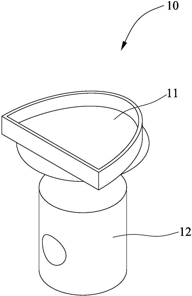
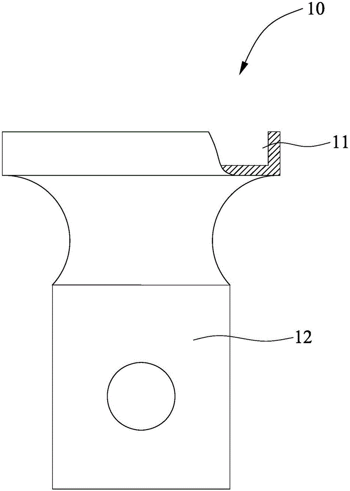
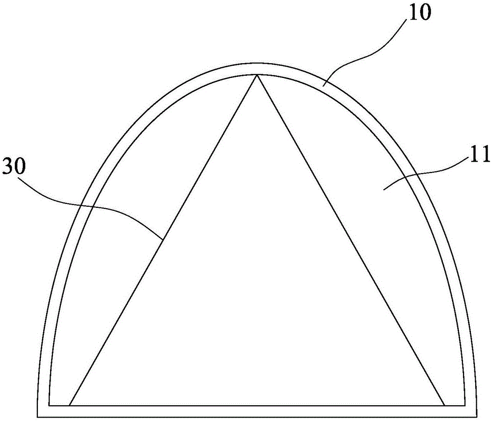
[0035] Pour the glue 20A into the glue tank 11 of the metal fixture 10, the thickness of the glue is 5mm, cut the filter material 30 of the cylinder body into a 300mm*80mm rectangle, and fold it in half along the long side into a "V" shape, that is, " Each side of the V" shape is 40mm long and the bend angle is 60°. Vertically insert the "V"-shaped edge of the filter material 30 into the glue 20A that has been poured into the metal fixture 10. After standing for 24 hours, the adhesive 20A is completely cured. The metal clamp 10 is fixed on the tensile strength machine with a pin, the filter material 30 is clamped with the clamp of the strength machine, and the tensile performance is tested at a pulling speed of 100 mm / min and the fracture mode is recorded. Repeat 3 samples. The test structure records of 3 samples are as follows:
[0036] Numbering
Embodiment 2
[0038] After mixing the two-component viscose 20B evenly in proportion, pour it into the glue tank 11 of the metal fixture 10. The thickness of the viscose 20B is 5mm. Cut the filter material 30 into a 300mm*80mm rectangle and align it along the long side. Half-folded into a "V" shape, that is, each side of the "V" shape is 40mm long and the bend angle is 60°. Vertically insert the "V"-shaped edge of the filter material 30 into the glue 20 that has been poured into the metal fixture 10. After standing for 8 hours, the adhesive 20B was completely cured. The metal clamp 10 is fixed on the tensile strength machine with a pin, the filter material 30 is clamped with the clamp of the strength machine, and the tensile performance is tested at a pulling speed of 100 mm / min and the fracture mode is recorded. Repeat 3 samples. The test structure records of 3 samples are as follows:
[0039] Numbering
Embodiment 3
[0041] Pour the viscose 20C into the glue tank 11 of the metal fixture 10, the thickness of the viscose 20C is 7mm, cut the filter material 30 of the cylinder body into a 300mm*80mm rectangle, and fold it in half along the long side into a "V" shape, namely Each side of the "V" shape is 40mm long, and the bend angle is 60°. Vertically insert the "V"-shaped edge of the filter material 30 into the glue 20C that has been poured into the metal fixture 10. After standing for 12 hours, the adhesive 20C is completely cured. The metal clamp 10 is fixed on the tensile strength machine with a pin, the filter material 30 is clamped with the clamp of the strength machine, and the tensile performance is tested at a pulling speed of 100 mm / min and the fracture mode is recorded. Repeat 3 samples. The test structure records of 3 samples are as follows:
[0042] Numbering
PUM
| Property | Measurement | Unit |
|---|---|---|
| Depth | aaaaa | aaaaa |
| Minor axis length | aaaaa | aaaaa |
Abstract
Description
Claims
Application Information
 - R&D
- Intellectual Property
- Life Sciences
- Materials
- Tech Scout
- Unparalleled Data Quality
- Higher Quality Content
- 60% Fewer Hallucinations
Browse by: Latest US Patents, China's latest patents, Technical Efficacy Thesaurus, Application Domain, Technology Topic, Popular Technical Reports.
© 2025 PatSnap. All rights reserved.Legal|Privacy policy|Modern Slavery Act Transparency Statement|Sitemap|About US| Contact US: help@patsnap.com


