Hydraulic bushing

A casing and hydraulic technology, applied in the direction of shock absorbers, springs, spring/shock absorbers, etc., can solve problems such as cost, and achieve the effect of simplifying access and filling

Active Publication Date: 2016-11-09
CONTITECH LUFTFEDERSYST
View PDF14 Cites 5 Cited by
  • Summary
  • Abstract
  • Description
  • Claims
  • Application Information

AI Technical Summary

Problems solved by technology

The length of the duct can be varied for setting the desired damping properties, however, the setting of the duct length is expensive in the central region of the device between the two chambers

Method used


Image

  • Hydraulic bushing
  • Hydraulic bushing
  • Hydraulic bushing

Examples


Embodiment Construction

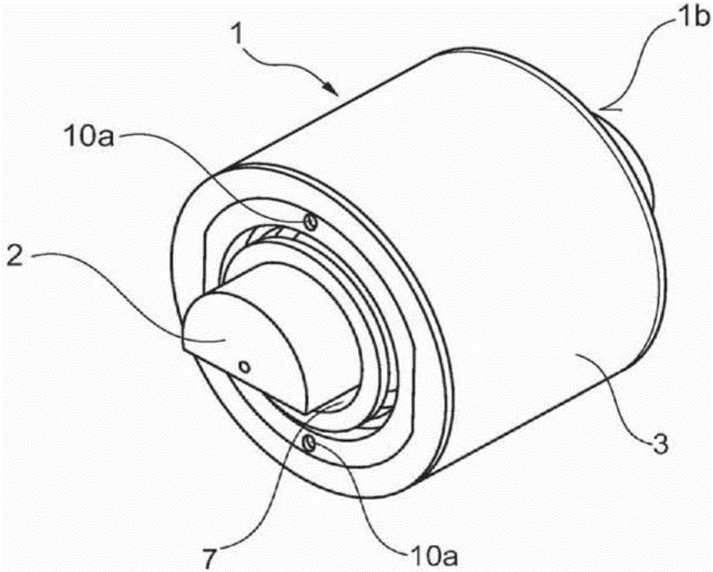
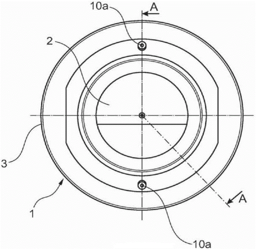
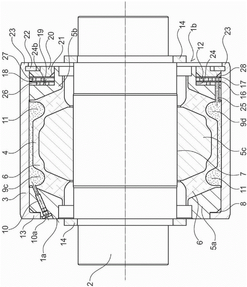
[0047] according to figure 1 A hydraulic bushing 1 according to the invention to be applied as a wheel set guide bushing for a rail vehicle is formed as a hollow cylinder which receives a steering pin 2 of a steering linkage of the rail vehicle. The steering pin 2 has a flattened portion for receiving the steering pin in the crossbar of the steering linkage in a rotationally fixed manner. The bushing 1 has a substantially sleeve-shaped outer housing element 3, for example in image 3 As shown in , the outer housing element radially surrounds an inner, substantially cylindrical housing element 5c forming an annular gap 4 . For example in image 3 As shown in , a rubber-elastic spring element, namely an annular spring element 6 , is arranged in the annular gap 4 .

[0048] At each end side 1a, 1b of the hydraulic bushing 1 there is arranged an axially outwardly arranged annular frame element 5a, 5b which co-operates with the housing elements 3, 5c and the annular spring eleme...


PUM


Abstract

The invention describes a bushing for a mount for the elastic connection of parts of a running gear, of a vehicle, in particular of a rail vehicle, and/or of movable machine elements, for receiving a journal of the running gear and/or of the machine elements in an axial receiving opening (7) which is defined by a substantially inner housing element (5c), which inner housing element is, at each face side of the bushing, at least partially encompassed by a radially encircling enclosure element (5a, 5b) and radially by an outer housing element (3), with the formation of a ring-shaped gap (4), wherein the ring-shaped gap is filled with a resiliently elastic material, such that at least two chambers (9c, 9d) that can be filled with a hydraulic fluid are formed between the outer housing element and the resiliently elastic material, which chambers are connected to one another via a connecting duct (12), and wherein the connecting duct is provided, outside the ring-shaped gap, in the ring-shaped enclosure elements. The invention also provides a bearing formed with the bushing.

Description

technical field [0001] The invention relates to a hydraulic bushing, in particular a wheel set guide bushing in a bearing for elastically connecting rail chassis components, wherein the hydraulic bushing has an inner housing element for Axial receiving opening for receiving a bolt and the inner housing element being radially contained by an outer housing element forming an annular gap, wherein an annular spring made of rubber elastic material is arranged in the annular gap element, wherein the annular spring element forms at least two cavities for the outer housing element that extend over subregions of its circumference and can be filled with hydraulic fluid, and these fillable cavities are passed through at least one connecting line / overflow pipes are connected to each other. Background technique [0002] Likewise, the invention relates to a bearing with such a hydraulic bushing, in particular in a bearing for resiliently connecting rail chassis components. [0003] Su...

Claims


Application Information

Patent Timeline
Patent Type & Authority Applications(China)
IPC IPC(8): F16F13/14F16F13/28
CPCF16F13/1463F16F13/28
Inventor 萨拉·穆罕默德-贝吉安德烈·桑斯
Owner CONTITECH LUFTFEDERSYST
Why Eureka
Try Eureka