
A kind of jack calibration tooling
A jack and nuclear tooling technology, applied in measuring devices, manufacturing tools, reinforcing molding, etc., can solve problems such as single effect, and achieve the effects of accurate length, reduction of pole cement consumption, crack resistance, ductility and stiffness enhancement.
- Summary
- Abstract
- Description
- Claims
- Application Information
AI Technical Summary
Problems solved by technology
Method used
Image

Examples
Embodiment 1
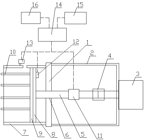
[0033] Such as figure 1 As shown: this embodiment provides a jack checking tool, including a baffle plate 1, a support foot 2 is provided on one side of the baffle plate 1, a jack 3 is provided on the support foot 2, and the jack 3 is connected by a connecting nut 4 is connected to the tension rod 5, a guide hole 6 is set in the middle of the baffle plate 1, the tension rod 5 passes through the guide hole 6, and a steel plate ring 7 is set on the other side of the baffle plate 1, and the steel plate ring 7 A tensioning plate 8 connected to the tensioning rod 5 is arranged inside, a rib plate 9 is arranged on the tensioning plate 8, and a rib plate 9 is connected with a steel bar 10, and a tension checking mechanism is arranged on the tensioning rod 5 11. The tension plate 8 is provided with a displacement check mechanism 12, and the steel ring 7 is provided with a sliding wire monitoring mechanism 13 corresponding to the steel bars 10.
[0034] When in use, the steel bar is h...
Embodiment 2
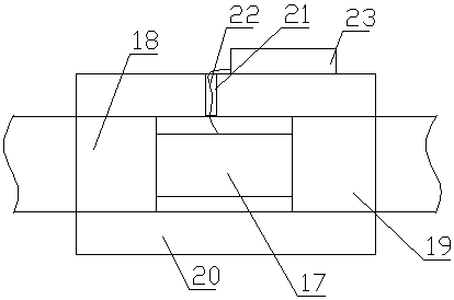
[0038] Such as figure 1 and figure 2 As shown: this embodiment provides a jack checking tool, including a baffle plate 1, a support foot 2 is provided on one side of the baffle plate 1, a jack 3 is provided on the support foot 2, and the jack 3 is connected by a connecting nut 4 is connected to the tension rod 5, a guide hole 6 is set in the middle of the baffle plate 1, the tension rod 5 passes through the guide hole 6, and a steel plate ring 7 is set on the other side of the baffle plate 1, and the steel plate ring 7 A tensioning plate 8 connected to the tensioning rod 5 is arranged inside, a rib plate 9 is arranged on the tensioning plate 8, and a rib plate 9 is connected with a steel bar 10, and a tension checking mechanism is arranged on the tensioning rod 5 11. The tension plate 8 is provided with a displacement check mechanism 12, and the steel ring 7 is provided with a sliding wire monitoring mechanism 13 corresponding to the steel bars 10.
[0039] The tension chec...
Embodiment 3
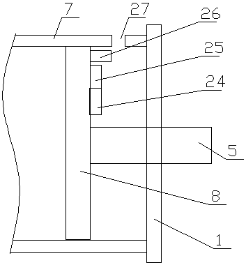
[0043] Such as figure 1 and image 3 As shown: this embodiment also provides a jack checking tool, including a baffle plate 1, a support foot 2 is provided on one side of the baffle plate 1, a jack 3 is arranged on the support foot 2, and the jack 3 is connected to The nut 4 is connected with the tension rod 5, a guide hole 6 is set in the middle of the baffle plate 1, the tension rod 5 passes through the guide hole 6, and the other side of the baffle plate 1 is provided with a steel ring 7, and the steel ring 7 is provided with a tensioning plate 8 connected to the tensioning rod 5, and a rib plate 9 is arranged on the tensioning plate 8, and the ribbing plate 9 is connected with a steel bar 10, and a tension check is set on the tensioning rod 5 Mechanism 11, a displacement checking mechanism 12 is set on the tensioning plate 8, and a sliding wire monitoring mechanism 13 is set on the steel ring 7 corresponding to the steel bar 10.
[0044] The displacement check mechanism ...
PUM
 Abstract
Description
Claims
Application Information