Check patentability & draft patents in minutes with Patsnap Eureka AI!

Joint mechanism for humanoid robot

A robot and human-like technology, applied in the direction of robots, manipulators, mechanical equipment, etc., can solve problems such as the reduction of torque transmission efficiency

Inactive Publication Date: 2016-11-16
NABLESCO CORP
View PDF6 Cites 4 Cited by
  • Summary
  • Abstract
  • Description
  • Claims
  • Application Information

AI Technical Summary

Problems solved by technology

Therefore, there is a possibility that the transmission efficiency of torque may decrease

Method used


Image

  • Joint mechanism for humanoid robot
  • Joint mechanism for humanoid robot
  • Joint mechanism for humanoid robot

Examples


Embodiment Construction

[0017] Hereinafter, an embodiment of the present invention will be described with reference to the drawings. However, for convenience of description, each of the drawings referred to below simplifies the main members necessary for the description of the present embodiment. Therefore, the joint mechanism of the humanoid robot according to the present embodiment may include arbitrary constituent members not shown in the drawings referred to in this specification.

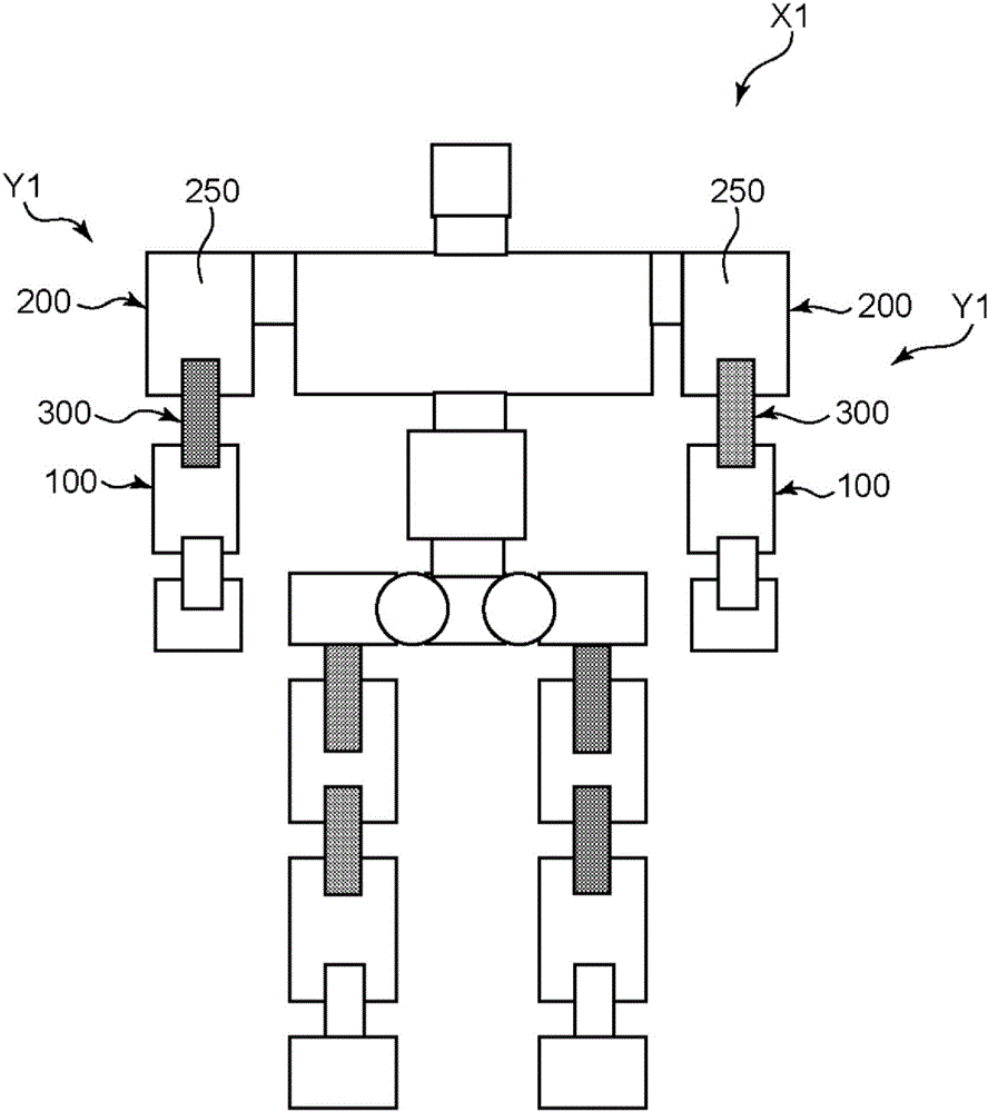
[0018] Such as figure 1 As shown, the humanoid robot X1 of this embodiment is a humanoid robot having a plurality of joints. The humanoid robot X1 includes a joint mechanism Y1, and the joint mechanism Y1 includes: a first member 100, which constitutes a part from the hand to an elbow; a second member 200, which constitutes a part from the elbow to a shoulder; and a gear device 300, which constitutes an elbow. part and realize the relative rotation between the first member 100 and the second member 200 . In additi...


PUM


Abstract

This joint mechanism (Y1) is equipped with: a first member (100); a second member (200); and a gear device (300) that performs conversion between the rotating speeds of the first member (100) and second member (200) at a predetermined rotating speed ratio and transmits a resulting driving force therebetween. The gear device (300) has: a crankshaft (10) on which a first eccentric part (10a) is formed; a first rocking gear (14) that has a first insertion hole (14b), through which the first eccentric part (10a) is inserted, and first external teeth (14a); a carrier (4) that holds the crankshaft (10); and an external cylinder (2) that has internal tooth pins (3). The gear device is constructed such that the carrier (4) and the external cylinder (2) are concentrically displaced with respect to each other by the rocking action of the first rocking gear (14).

Description

technical field [0001] The invention relates to a joint mechanism of a humanoid robot. Background technique [0002] Conventionally, there is known a joint mechanism of a humanoid robot in which a first member and a second member are relatively rotatable via a reducer. Patent Document 1 describes a joint mechanism in which a main body upper half and a main body lower half are connected via a harmonic drive (Harmonic Drive: registered trademark) as a speed reducer. In this joint mechanism, the harmonic gear device has a ring-shaped internal gear as a fixed-side gear and an elastic external gear as an output-side gear that meshes with and rotates with the ring-shaped internal gear, and the upper shaft portion of the lower half of the main body is fixed to the The ring-shaped internal gear, and the main body casing of the upper half of the main body are fixed to the elastic outer gear, so that the upper half of the main body and the lower half of the main body can relatively r...

Claims


Application Information

Patent Timeline
Patent Type & Authority Applications(China)
IPC IPC(8): B25J17/00F16H1/32
CPCB25J9/102B25J17/0241F16H1/32F16H2001/325Y10S901/25Y10S901/28F16H2001/323
Inventor 安藤清王宏猷牧添義昭岛田英史长谷隆之
Owner NABLESCO CORP
Features
  • R&D
  • Intellectual Property
  • Life Sciences
  • Materials
  • Tech Scout
  • Unparalleled Data Quality
  • Higher Quality Content
  • 60% Fewer Hallucinations
Learn More